LED lightbulb with improved gain structure

Inactive Publication Date: 2012-02-09
YEN HSU LI
View PDF7 Cites 3 Cited by
  • Summary
  • Abstract
  • Description
  • Claims
  • Application Information

AI Technical Summary

Benefits of technology

[0010]An LED lightbulb with an improved gain structure, configured to improve LED lamp pattern design and arrangement of light-emitting dies, has a die-type LED lamp with the light-emitting dies desirably arranged and a structure for preventing insects from intruding into the lamp, including a base casing, a heat dissipating unit coupled with the LED lamp, meshes, and a transparent cover, and characterized in that the LED lamp has a middle portion defined with a matrix arrangement region for the light-emitting dies. Rows of the light-emitting dies are disposed at the periphery of the matrix arrangement region. The light-emitting dies disposed at the periphery of the matrix arrangement region are spaced apart from the light-emitting dies disposed within the matrix arrangement region, respectively. The meshes adhere to the base casing and correspond in position to the air holes, respectively, to prevent intrusion of insects and thereby protect the LED lamp against short circuits.

Problems solved by technology

Also, there are growing concerns for the manufacturing process of lamps, raw materials used in the process, environmental protection-related issues regarding the recycling of the raw materials, and high power consumption of light.
Recently, there are some instances of unfavorable international coverage of the negative effect of conventional lamps on the human health and environmental protection.
However, insects are likely to intrude into the LED lamps through such ventilation holes to thereby cause short circuits to the LED lamps.
Also, light-emitting dies of LED lamps are usually arranged in a matrix and thus fail to meet the need for a wide variety of lamp patterns (that is, patterns other than a matrix).

Method used


Image

  • LED lightbulb with improved gain structure
  • LED lightbulb with improved gain structure
  • LED lightbulb with improved gain structure

Examples


Embodiment Construction

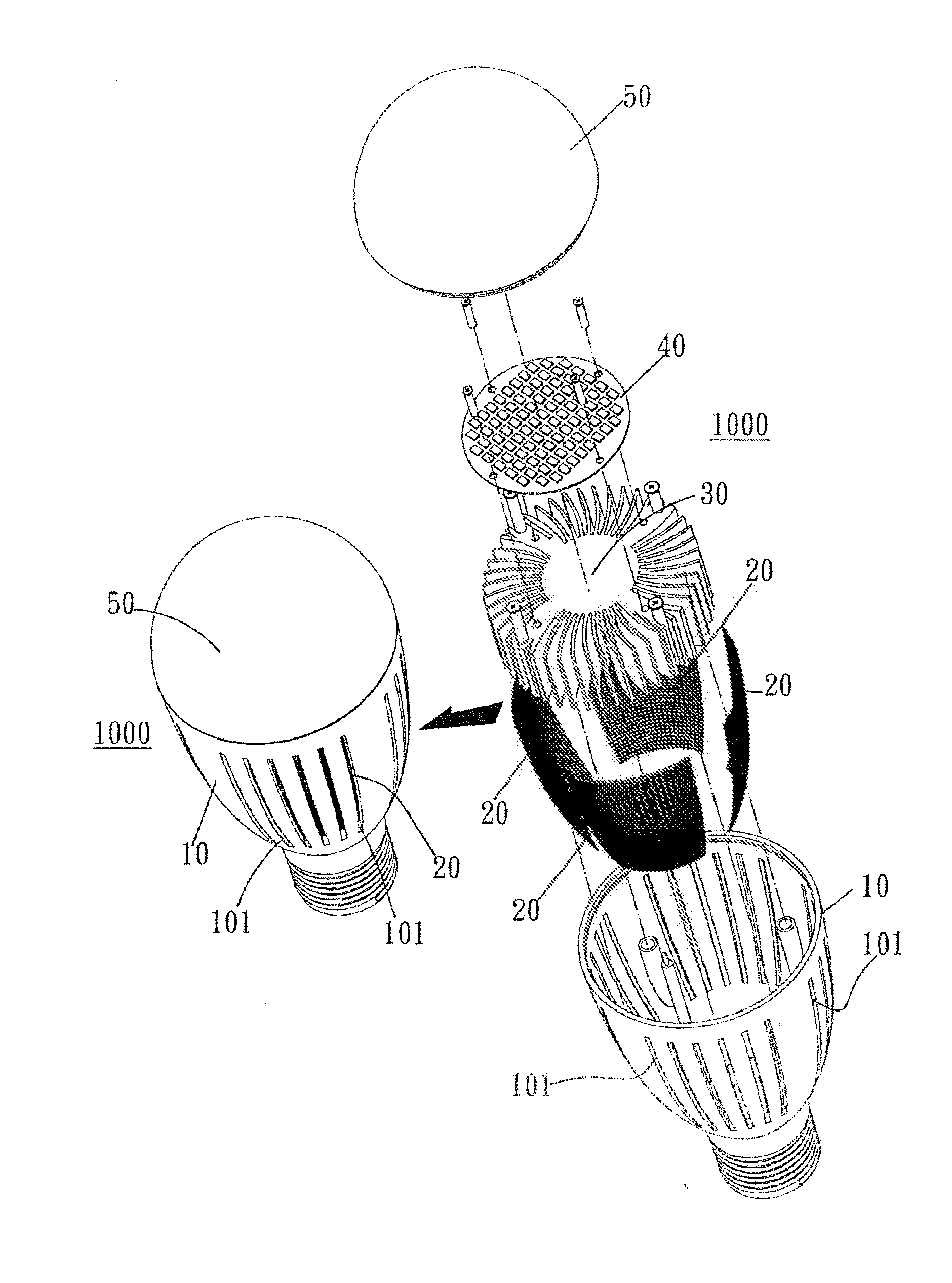
[0014]FIG. 1 is a schematic perspective view of an assembled LED lightbulb with an improved gain structure of the present invention. As shown in the drawing, an LED lightbulb 1000 with an improved gain structure according to the present invention comprises: a base casing 10 with a plurality of air holes 101; meshes 20 adhering to an inner side of the base casing 10 and corresponding in position to the air holes 101, respectively; a heat dissipating unit 30 coupled to the inside of the base casing 10; an LED lamp 40 coupled with heat dissipating unit 30; and a transparent cover 50 positioned atop, wherein the meshes 20 prevent insects from intruding into the LED lightbulb 1000 through the air holes 101, thereby protecting the LED lightbulb 1000 against short circuits.

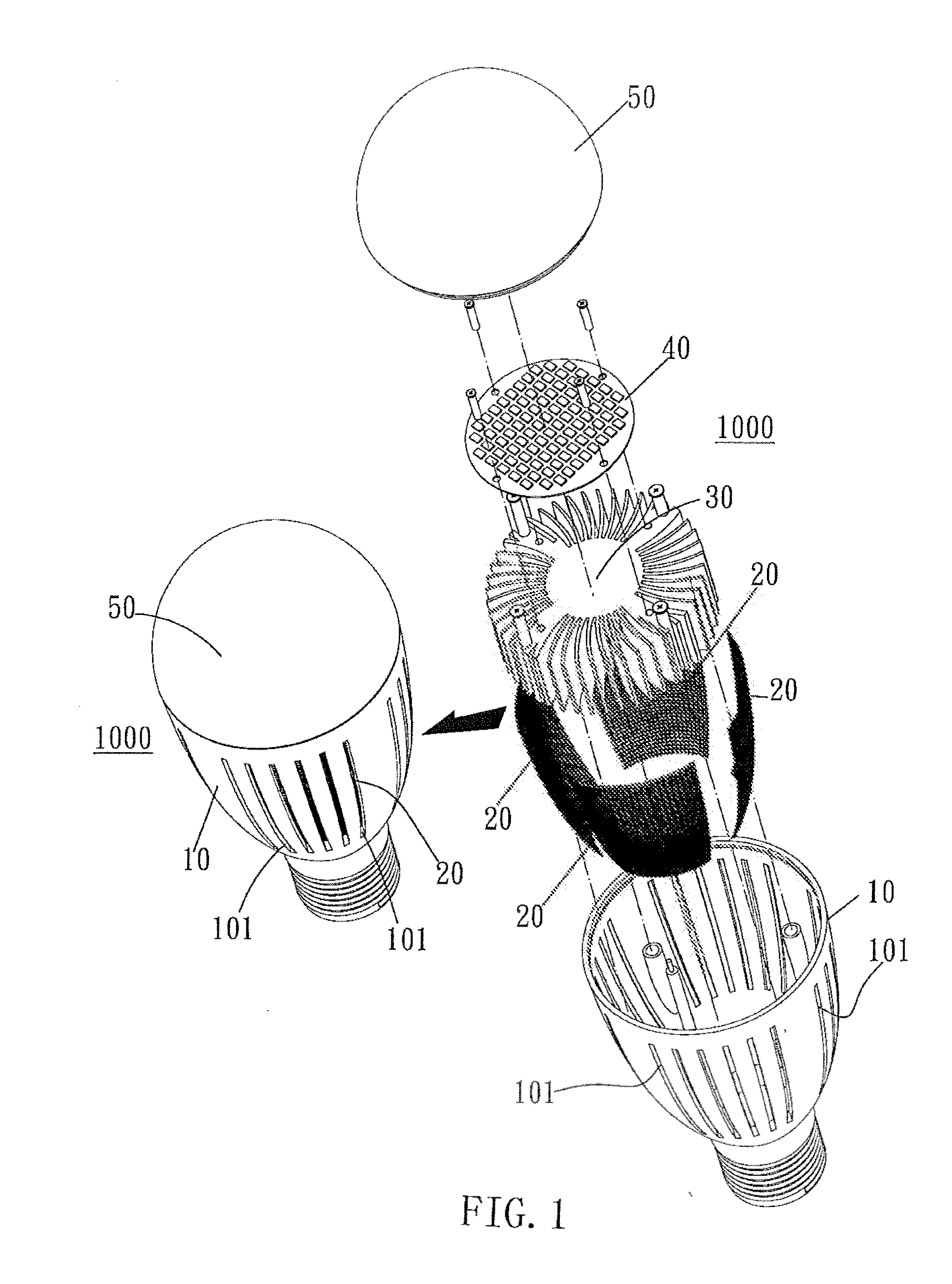
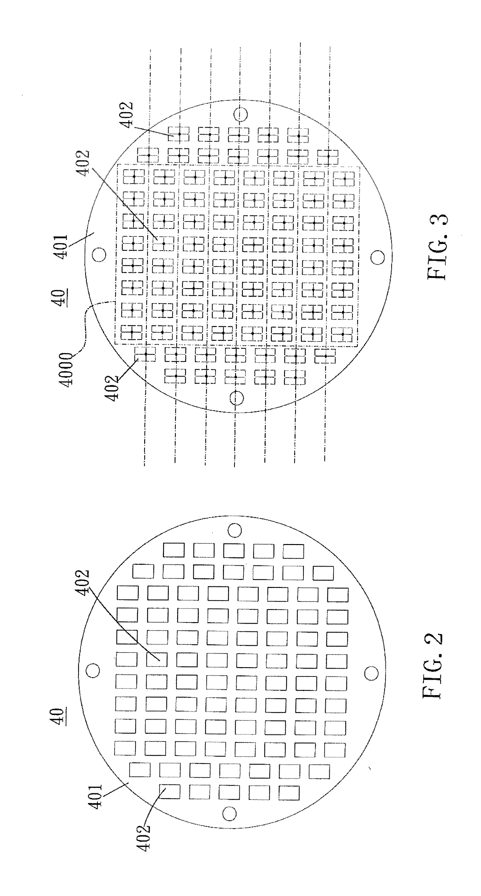
[0015]FIG. 2 is a schematic view of an LED lamp of the present invention. As shown in the drawing, light-emitting dies 402 are disposed across a substrate 401. Referring to FIG. 3, which is a concise schematic view of th...


PUM


Abstract

An LED lightbulb with an improved gain structure has a die-type LED lamp with the light-emitting dies arranged and a structure for preventing insects from intruding into the lamp, including a base casing, a heat dissipating unit coupled with the LED lamp, meshes, and a transparent cover, and characterized in that the LED lamp has a middle portion defined with a matrix arrangement region for the light-emitting dies. Rows of the light-emitting dies are disposed at the periphery of the matrix arrangement region. The light-emitting dies disposed at the periphery of the matrix arrangement region are spaced apart from the light-emitting dies disposed within the matrix arrangement region, respectively. The meshes adhere to the base casing and correspond in position to the air holes, respectively, to prevent intrusion of insects and thereby protect the LED lamp against short circuits.

Description

BACKGROUND OF THE INVENTION[0001]1. Technical Field[0002]The present invention relates LED lamps, and more particularly, to an LED lightbulb with an improved gain structure.[0003]2. Description of Related Art[0004]Living spaces nowadays are illuminated by various lamps. In spaces, lamps are positioned as needed and configured to emit light for providing brightness in the spaces. Hence, lighting equipment is important to living spaces, as the light it emits not only enhances the quality of the living spaces, but is closely correlated with the health of the human body and the human eye.[0005]In general, basic lighting is intended to illuminate a space and thereby ensure an unblocked view thereof. Hence, the stability of the light emitted by basic lighting has a direct effect on the human eye. Also, there are growing concerns for the manufacturing process of lamps, raw materials used in the process, environmental protection-related issues regarding the recycling of the raw materials, a...

Claims


Application Information

Patent Timeline
IPC IPC(8): F21S8/00
CPCF21K9/135F21Y2101/02F21Y2105/001F21V29/83F21V15/00F21V19/0055F21V29/74F21V3/00F21Y2105/10F21K9/232F21Y2115/10
Inventor YEN, HSU LI
Owner YEN HSU LI
Why Eureka
Try Eureka