Speed change control system for transmission of vehicle

a technology of transmission system and speed change ratio, which is applied in the direction of gearing control, mechanical equipment, gearing, etc., can solve the problems of affecting the operation of the transmission system, the device applicable to the mechanism taught by japanese patent laid-open no. 6-257655 has to be limited, and the transmission has to be enlarged entirely. , to achieve the effect of easy control of the tilt angle of the rolling member, easy synchronization of rotational speed, and easy control

Active Publication Date: 2012-02-09
TOYOTA JIDOSHA KK
View PDF5 Cites 95 Cited by
  • Summary
  • Abstract
  • Description
  • Claims
  • Application Information

AI Technical Summary

Benefits of technology

[0024]As also described, the control system of the present invention comprises the neutral command means. Therefore, the rolling member can be tilted widely in both positive and negative directions to carry out the synchronous control on the occasion of carrying out the subsequent speed change operation. For this reason, the tilt angle of the rolling member can be controlled easily in the subsequent speed change operation.
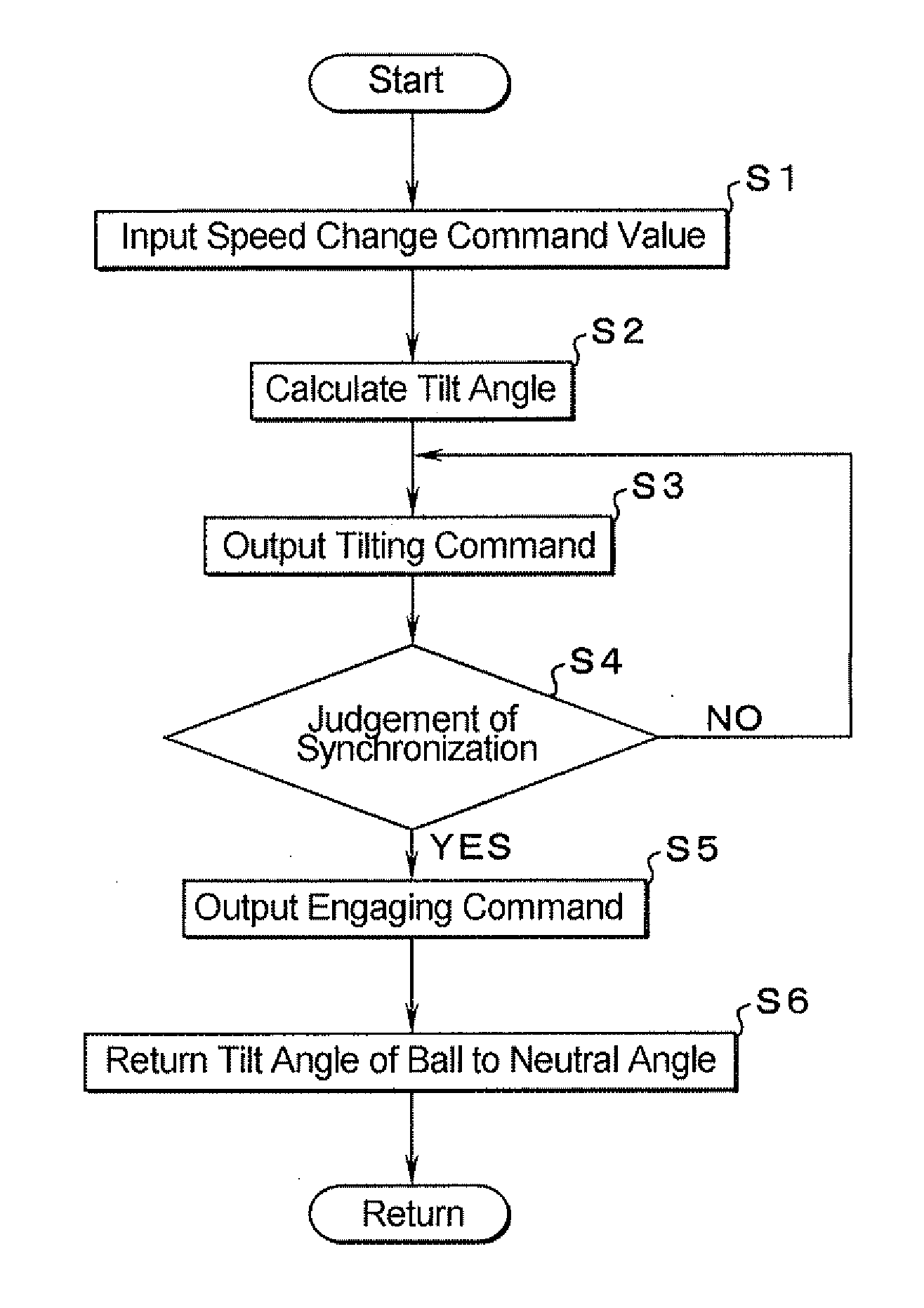
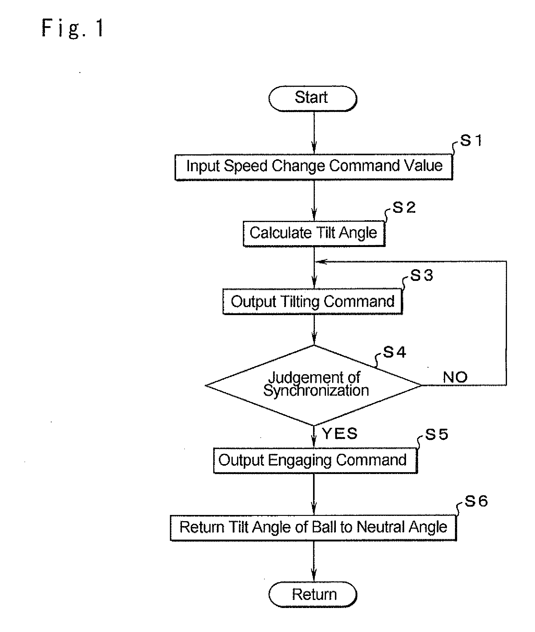
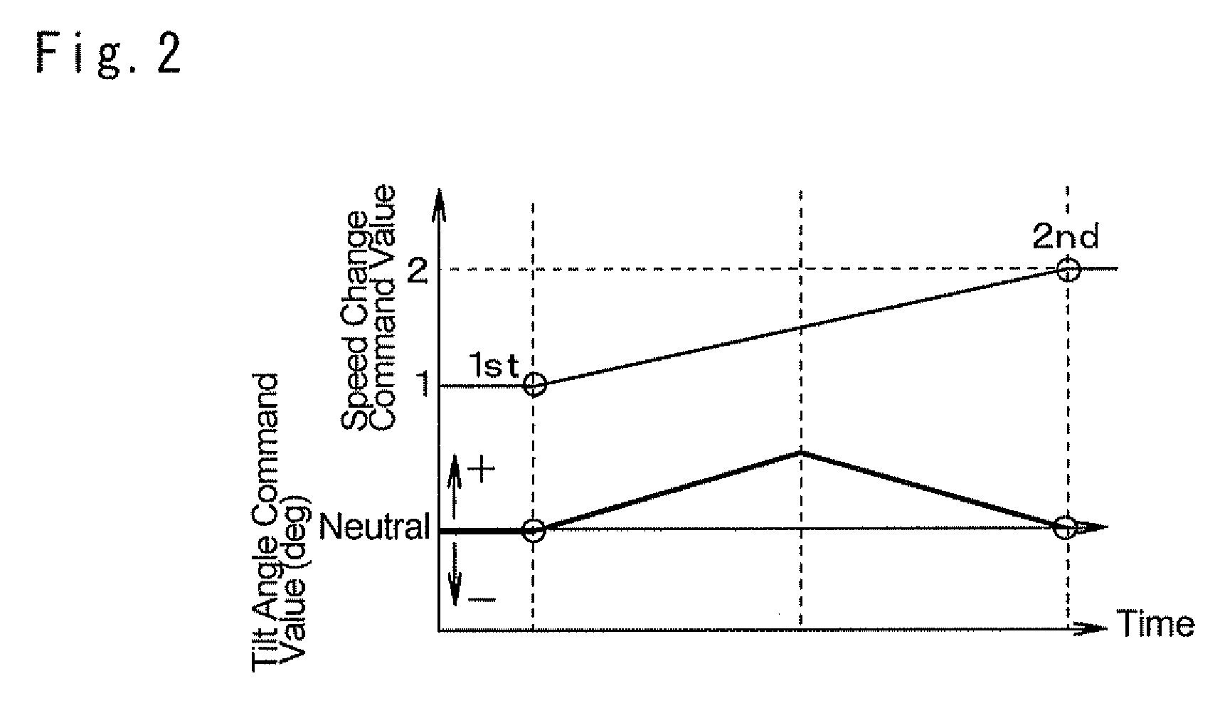
[0025]Further, the control system of the present invention comprises the tilt angle control means. Therefore, the tilt angle of the rolling member is returned to the neutral angle at which the speed change ratio of the continuously variable transmission mechanism becomes “1”, after said difference in the rotational speeds becomes smaller than the preset value and the switching mechanism is therefore shifted to be engaged. For this reason, said rotational speeds can be synchronized by tilting the rolling member in a manner to set an intermediate speed change ratio between the gear stages of the geared transmission mechanism. Thus, the tilt angle of the rolling member can be controlled easily and said rotational speeds can be synchronized easily.
[0026]According to the present invention, in case of carrying out the synchronous control by the continuously variable transmission mechanism, the change rate of the speed change ratio can be reduced relatively just before said difference in the rotational speeds becomes smaller than the preset value. Therefore, a difference in the rotational speed of the switching mechanism and the rotational speed of the member to be engaged with the switching mechanism can be reduced when the switching mechanism is engaged with the member ...

Problems solved by technology

Therefore, the transmission has to be enlarged entirely, and energy efficiency thereof may be deteriorated.
Therefore, devices applicable to the mechanism taught by Japanese Patent Laid-Open No. 6-257655 have t...

Method used


Image

  • Speed change control system for transmission of vehicle
  • Speed change control system for transmission of vehicle
  • Speed change control system for transmission of vehicle

Examples


Embodiment Construction

[0051]Next, this invention will be described in connection with its specific examples. The transmission of the present invention to be used in a vehicle is structured by connecting a continuously variable transmission and a geared transmission in series. An example of the continuously variable transmission (i.e., a DUO-CVT) 1 is shown in FIG. 15. In the continuously variable transmission mechanism 1, a torque is transmitted among three rotary elements (or rotary member). Specifically, the continuously variable transmission mechanism 1 is configured to vary a speed change ratio between a first rotary member functioning as an input member and a second rotary member functioning as a first output member continuously and steplessly, and to vary a speed change ratio between the input member and a third rotary member functioning as a second output member continuously and steplessly. In FIG. 15, reference numeral 2 represents an input shaft, and a roller 3 is fitted onto the input shaft 2 t...


PUM


Abstract

To provide a control system for carrying out a speed change operation of a geared transmission mechanism continuously by controlling a continuously variable transmission mechanism.
A continuously variable transmission mechanism configured to increase and decrease speeds of a first and a second output discs simultaneously, and a geared transmission mechanism configured to change a speed change ratio stepwise are connected in series. The output discs are connected individually with intermediate shafts. The control system is adapted to synchronize a rotational speed of a switching mechanism and a rotational speed of a member to be engaged with the switching mechanism, by tilting a rolling member when carrying out a speed change in the geared transmission mechanism thereby increasing a rotational speed of one of the intermediate shaft while decreasing a rotational speed of the other intermediate shaft (at steps S3, S4 and S5).

Description

TECHNICAL FIELD[0001]This invention relates to a system for controlling a speed change ratio of a transmission of a vehicle, and especially to a system for controlling a speed change ratio of a transmission structured by combining a continuously variable transmission mechanism and a geared transmission mechanism.BACKGROUND ART[0002]A transmission, in which a geared transmission unit comprising gear pairs, and a switching mechanism selectively allowing and disabling the gear pairs to transmit a torque between an input shaft and an output shaft, is connected in series with a mechanism capable of varying a speed change ratio thereof continuously is known in the prior art. For example, the transmission of this kind is disclosed in Japanese Patent Laid-Open No. 2007-177925 and Japanese Patent Laid-Open No. 2003-113934. Specifically, according to the transmission taught by the above-listed documents, gear pairs for setting gear stages are arranged on two intermediate shafts and an output ...

Claims


Application Information

Patent Timeline
IPC IPC(8): F16H61/66F16H37/02F16H15/52F16H61/02F16H61/68
CPCF16H3/12F16H15/52F16H61/0403F16H61/6649F16H63/065
Inventor OGAWA, HIROYUKIMURAKAMI, AKIRA
Owner TOYOTA JIDOSHA KK
Why Eureka
Try Eureka