Device and method for measuring anatomic geometries

a technology of anatomic geometries and devices, applied in medical science, surgery, diagnostics, etc., can solve the problems of deficient devices, systems and methods utilizing prior ar

Inactive Publication Date: 2012-02-09
MARYLAND UNIV OF
View PDF17 Cites 164 Cited by
  • Summary
  • Abstract
  • Description
  • Claims
  • Application Information

AI Technical Summary

Benefits of technology

[0009]The present invention is directed to a device for measuring an object geometry. The device comprises a probe having a distal contacting end and a proximal tracking end, means for tracking a location of the contacting end of the probe positioned near the proximal end electronically connected to the contacting end of the probe and an actuation control unit electronically connected with at least the tracking sensor. A related device further comprises a measurement and post processing unit electronically connected with one or both of the tracking sensor or the actuation control unit. Another related device further comprises means for holding the probe that is positioned at the proximal end of the probe.

Problems solved by technology

Particularly, the prior art is deficient in devices, systems and methods utilizing direct touch to measure and image anatomic defects or anatomic geometries in a subject.

Method used


Image

  • Device and method for measuring anatomic geometries
  • Device and method for measuring anatomic geometries
  • Device and method for measuring anatomic geometries

Examples


example 1

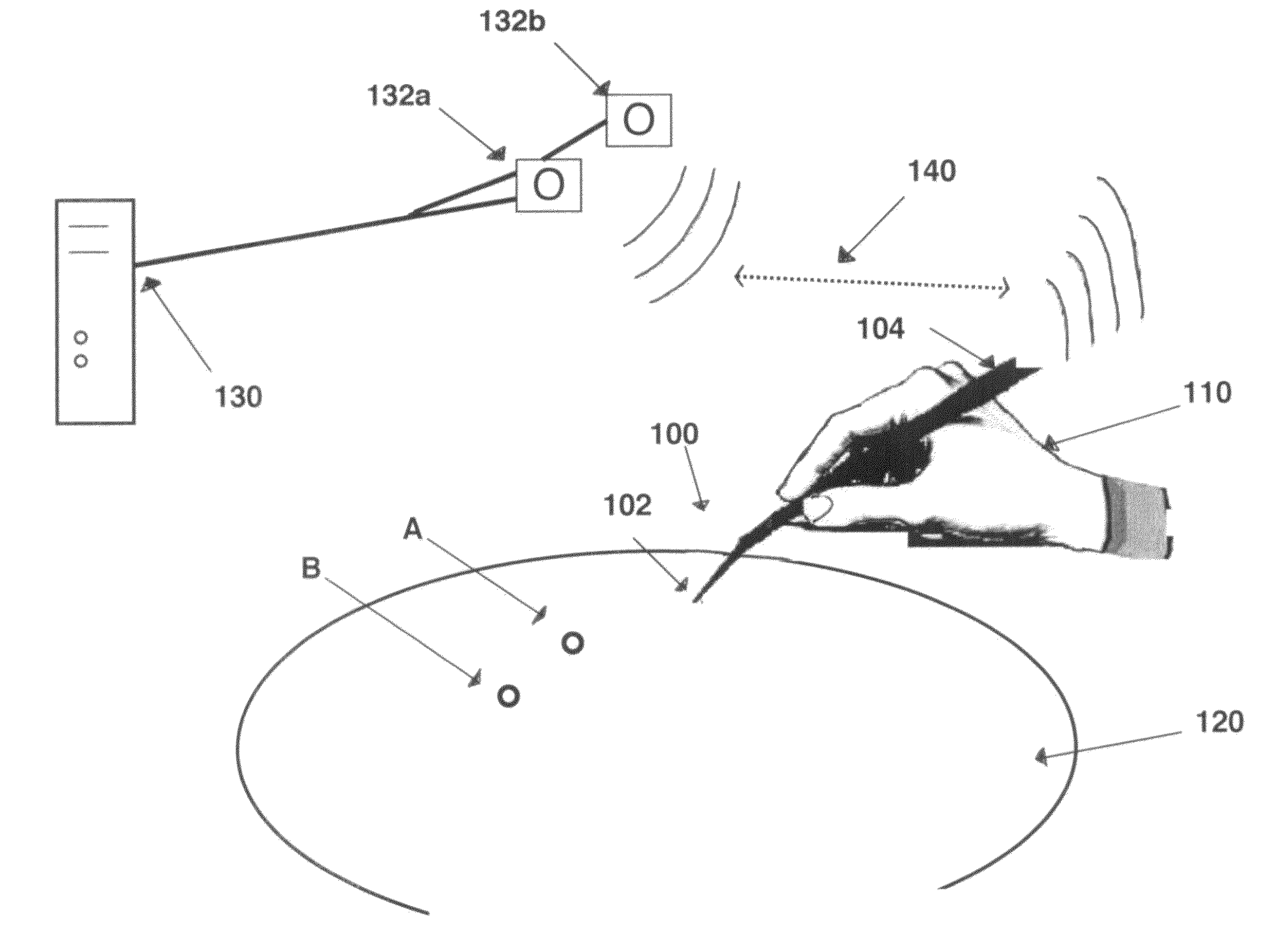
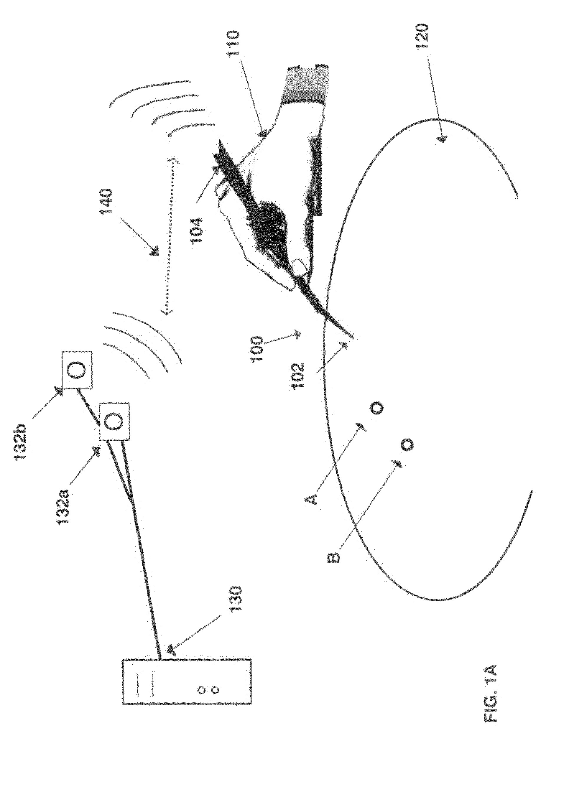
[0072]Measurement with the Probe

Probe Calibration

[0073]This calibration process is required for all possible motion tracking technologies. With most motion tracking systems, it is physically impossible to attach the tracking sensor at the tip of probe. With some motion tracking technologies such as electromagnetic motion tracking, the sensor may be attached to the tip of the probe but this creates another issue in sterilization of the sensors. To avoid these problems, the motion sensor is placed at the proximal position, that is, near the handle of the probe. Then a calibration process is required to define the relative location (x, y, z in three dimensional space) of the tip of probe with reference to the coordinate center defined at the location of tracking sensor.

[0074]The coordinate center for each tracking sensors are defined according to the type of tracking utilized. In optical tracking with an array of reflective markers the coordinate center is the physical center location ...

example 2

Operation Procedures for Measurement

General Overview

[0078]The system power is turned on. The probe is then introduced into the body to verify whether the tip of the probe can reach target. A continuous or discrete mode is selected from a control panel. A system / data acquitsion or start is initiated via, for example, a mouse, a foot pedal, a voice activation system, and / or gestured controlled system. Data collection begins, i.e., linear or point-to-point.

Discreet Mode: Line Segment

[0079]The operator moves the probe tip to a point of interest (initial point) and then activates data collection mode is activated (options: holding the data button, pushing a pedal switch, or saying “Start”). Two seconds after activating the data collection mode, the operator gets a confirmation, audible and / or visible, e,g., hears a continuous auditory tone which confirms that the data is being collected. The operator then moves to the final point of interest and activates data collection mode (options: h...

example 3

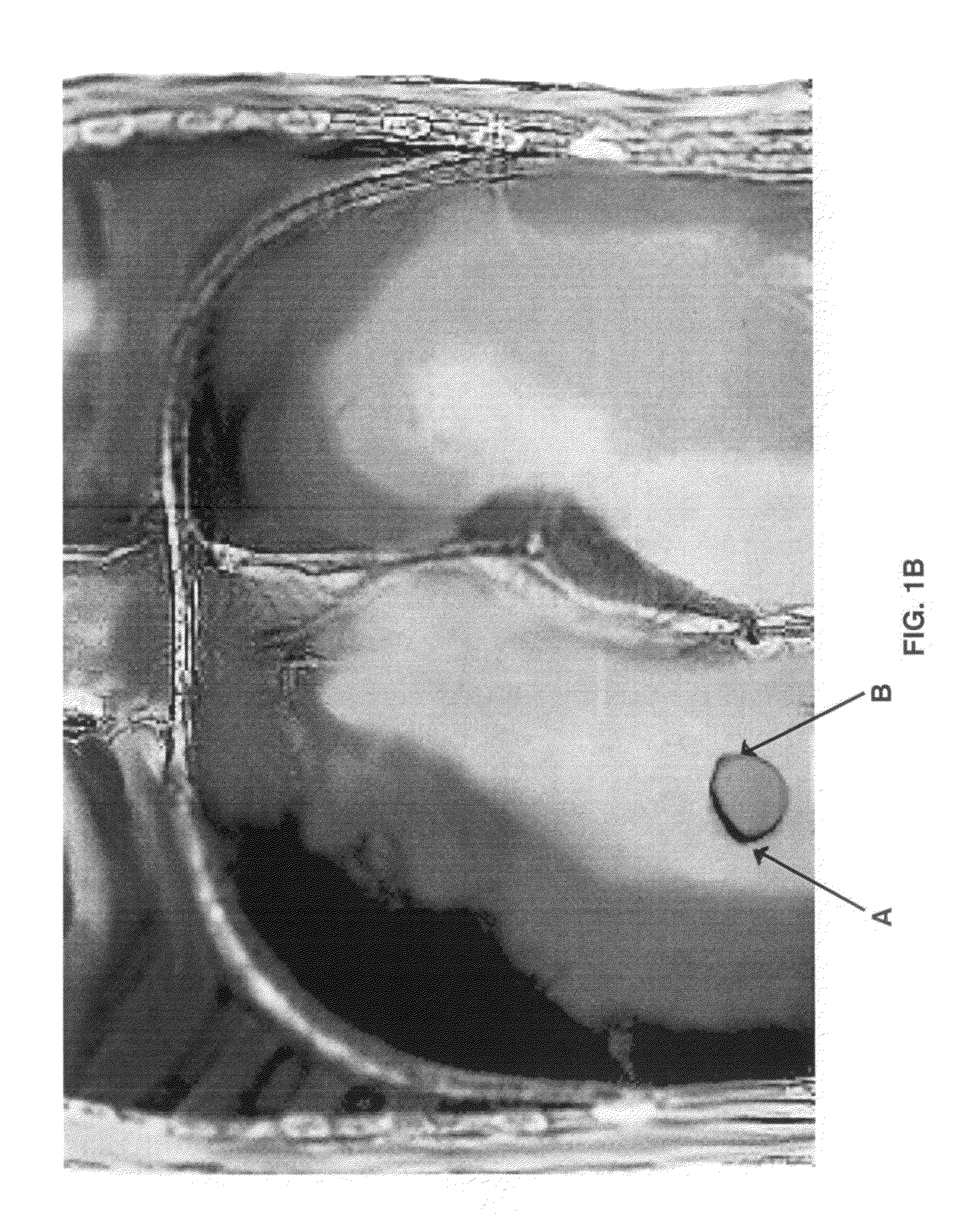
Measuring a Hernia Defect

[0083]The calibration and operation procedures for measuring a hernia defect in discrete mode, utilizing point-to-point, linear or non-linear, circumferential, or continuous data acquisition methods are substantially identical to the operation of the device as described in Examples 1 and 2. In a discrete mode for circumference measurement of the defect, after data collection is terminated, the system initiates a process called “Hernia Estimation”.

[0084]In “Hernia Estimation” the system displays simplified two-dimensional geometry of the hernia defect and the operator responds to the question “Will you accept this estimation (Yes / No). If the operator selects “No”, the operator will repeat the above steps until the operator obtains an acceptable estimation. If the operator selects “Yes”, the system will display a message “Estimation accepted”.

[0085]The operator selects options for the estimation of mesh shape (Oval / Specific). For an oval, the system creates an...


PUM


Abstract

Provided herein is a device and system for measuring an object geometry. The device comprises a probe with contacting and tracking ends and a tracking means and actuation control unit positioned on the probe. The system further comprises a measurement and post processing unit in electronic communication with the tracking means and/or the actuation control unit. Also provided is a method for measuring a geometry of an anatomic object, for example, a hernia. One or more locations of interest on the object are touched directly with the contacting probe end and the location or motion data of the probe end and of the tracking means are tracked and transmitted to the measurement and post processing unit as the point(s) of interest are touched. The data is processed into the geometric measurement and a representative image may be displayed.

Description

CROSS-REFERENCE TO RELATED APPLICATIONS[0001]This non-provisional patent application claims benefit of provisional patent application U.S. Ser. No. 61 / 366,551, filed Jul. 22, 2010, now abandoned, the entirety of which is hereby incorporated by reference.BACKGROUND OF THE INVENTION[0002]1. Field of the Invention[0003]The present invention relates generally to the fields of biomedical devices and surgery. More specifically, the present invention provides a device and methods for measuring 2nd- and 3rd-dimensional anatomic defects and / or geometries utilizing direct touch and indirect measurements.[0004]2. Description of the Related Art[0005]Current methods of determining location, size or other measurements of anatomic features, particularly for surgical purposes, require the use of measuring devices such as tape measures or other calibrated apparatuses which can be positioned internally along the feature or defect. Measurements are taken by direct visualization or from an image of the...

Claims


Application Information

Patent Timeline
Patent Type & Authority Applications(United States)
IPC IPC(8): A61B5/107A61B1/00
CPCA61B1/0008A61B1/00147A61B1/00158A61B5/107A61B2017/00203A61B5/6847A61B2090/3983A61B2034/2068A61B34/20A61B1/00097
Inventor GEORGE, IVANLEE, GYUSUNGPARK, ADRIAN
Owner MARYLAND UNIV OF
Why Eureka
Try Eureka