Laser-transparent tape measure

Inactive Publication Date: 2012-02-16
MCCARTHY RONALD J
View PDF6 Cites 64 Cited by
  • Summary
  • Abstract
  • Description
  • Claims
  • Application Information

AI Technical Summary

Benefits of technology

[0013]Accordingly, it is an object of the present invention to provide tape measure having a translucent window adapted for use with a dot laser and having a predetermined return loss (difference between power incident upon t

Problems solved by technology

However, with a standard measuring tape, the worker often needs to see underneath the tape to view the laser dot.
However, these instruments are intended for measuring atop architectural drawings, and not for displaying a l

Method used


Image

  • Laser-transparent tape measure
  • Laser-transparent tape measure
  • Laser-transparent tape measure

Examples


Embodiment Construction

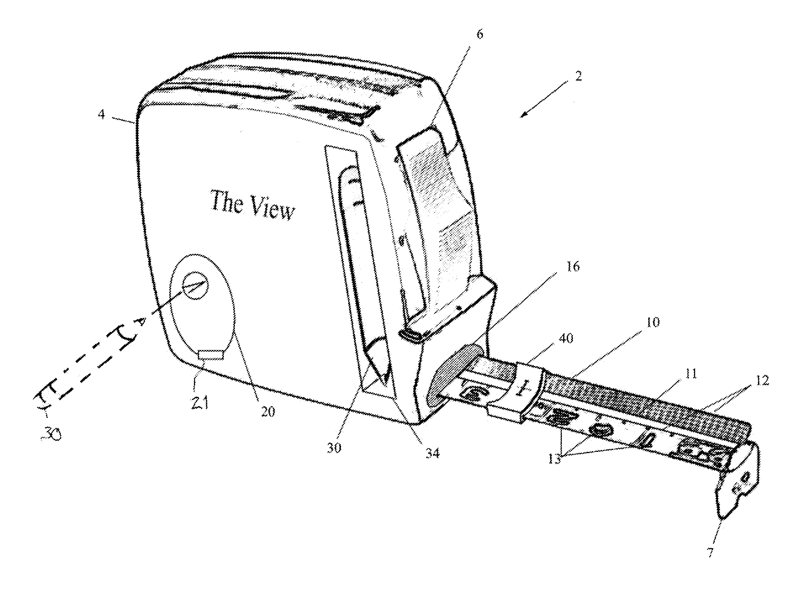
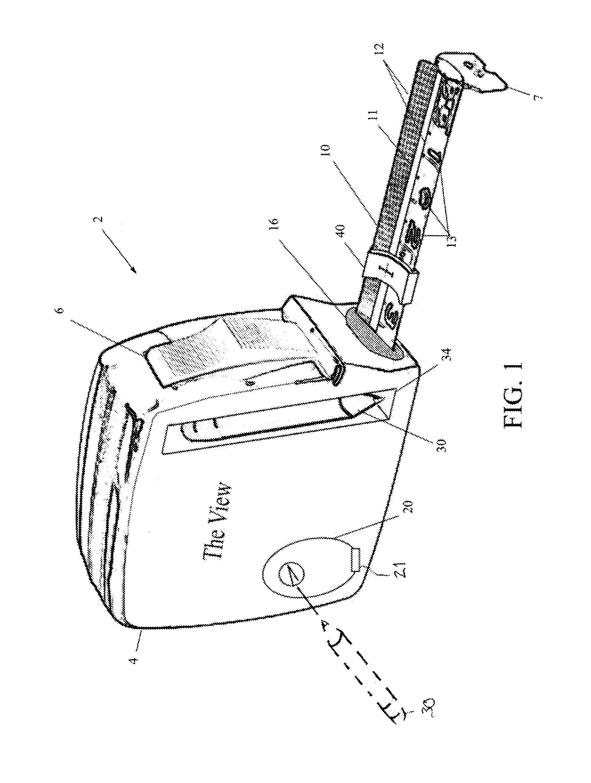
[0028]Reference will now be made in detail to preferred embodiments of the present invention, examples of which are illustrated in the accompanying drawings. Wherever possible, the same reference numbers will be used throughout the drawings to refer to the same or like parts. Hereinafter, a laser-translucent tape measure is described which is useful in taking or making measurements when using a construction laser, because the uncoiled tape allows partial transmission of a laser beam there through, so that a laser beam shining on one side of the tape will appear as a dot on the other side of the tape. This allows a worker to see the laser through the tape.

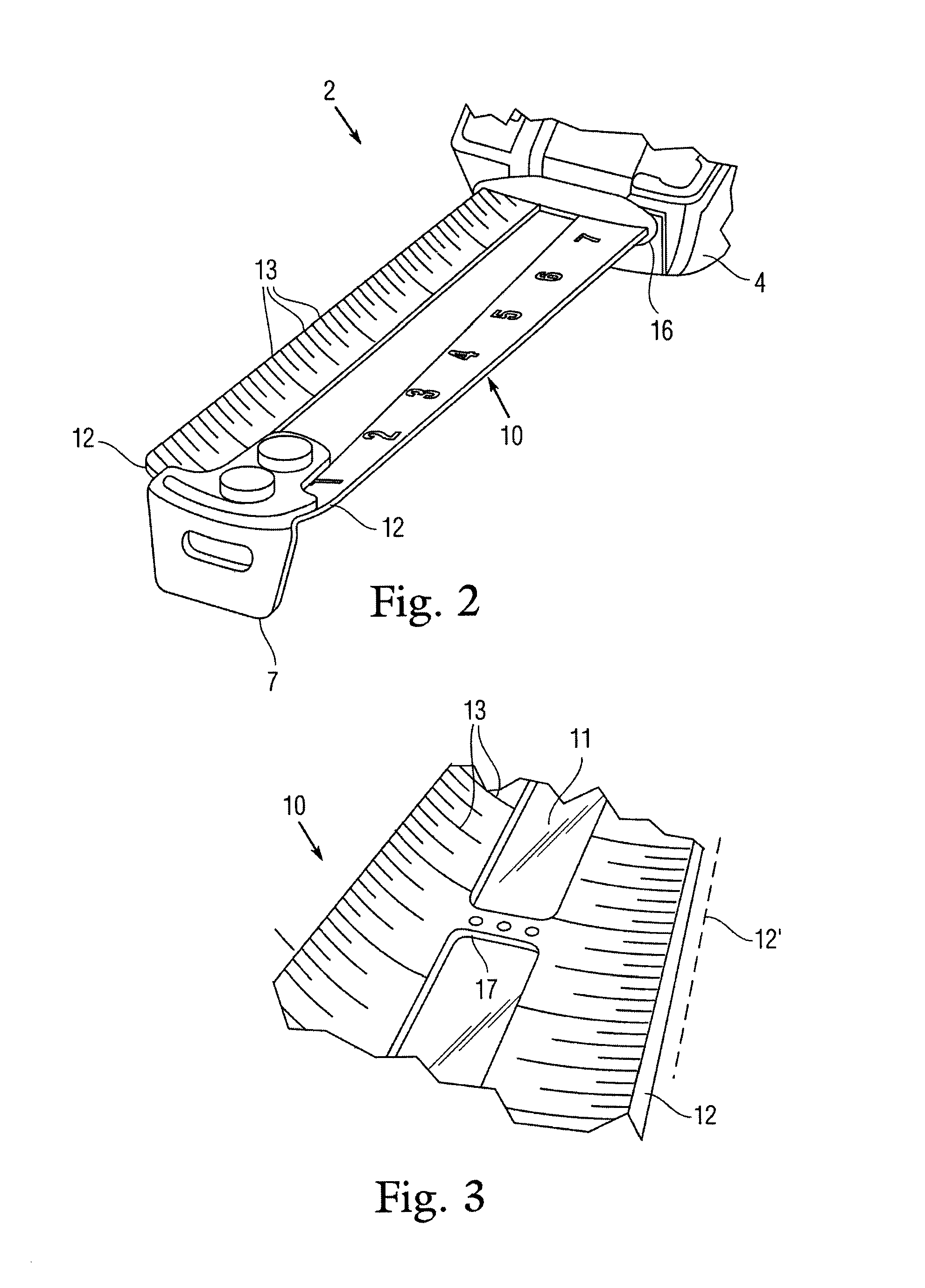
[0029]FIG. 1 is a perspective view of the laser-translucent tape measure 2 according one embodiment of the present invention. The tape measure 2 generally includes a partially translucent tape 10 formed as a split tape with opposing opaque margins 12 marked with measuring indicia 13, and an elongate translucent window 11 running len...


PUM


Abstract

A tape measure having an integral pencil sharpener specifically for square contractor pencils, and a retractable tape formed with opposing indexed metal edges flanking a central elongate transparent or translucent window for allowing a laser beam to shine centrally through.

Description

CROSS REFERENCE TO RELATED APPLICATIONS[0001]This application derives priority from U.S. provisional application Ser. No. 61 / 299,057 filed 28 Jan. 2010, which is hereby incorporated by reference as if fully set forth herein.BACKGROUND OF THE INVENTION[0002]1. Field of the Invention[0003]The present invention relates to hand tools and, more particularly, to a laser-transparent measuring tape useful in combination with a laser for making precise measurements on construction projects.[0004]2. Discussion of the Related Art[0005]A plumb-bob or a plummet is a weight that is suspended from a string and used as a vertical reference line, or plumb-line. The plumb bob was used by the early Egyptians to ensure that constructions are “plumb”, or vertical. Tape measures are comparatively newer and yet more ubiquitous instruments. Tape measures typically comprise a coiled cloth or metal strip with linear-measurement markings. The flexibility allows for a measure of significant length to be easily...

Claims


Application Information

Patent Timeline
IPC IPC(8): G01B3/10
CPCB43K23/001B43L23/00G01B3/1041G01B3/1082G01B3/1084G01B2003/1046G01B2003/1048G01B2003/1089G01B3/1003G01B3/1046G01B3/1048G01B3/1089
Inventor MCCARTHY, RONALD J.
Owner MCCARTHY RONALD J
Why Eureka
Try Eureka