Light scanner and image forming apparatus

Active Publication Date: 2012-02-16
SEIKO EPSON CORP
View PDF5 Cites 5 Cited by
  • Summary
  • Abstract
  • Description
  • Claims
  • Application Information

AI Technical Summary

Benefits of technology

[0009]According to the light scanner, the light reflection surface is displaced in conjunction with the movable part and reflects incident light in an arbitrary direction. The movable part is displaced with activation of the movable beams driven by the displacement part of a first drive unit. Here, in a non-driven state, the movable beam has a form extending along a first axis as one axis with the displacement part on a surface in parallel to the light reflection surface, and the displacement part is supported by the drive beam extending in the orthogonal direction to the movable beams on the surface in parallel to the light reflection surface. That is, by the rotation of the displacement part around the drive beam, the pair of movable beams with the movable part in between respectively rotate and displace the movable part. Then, the bending part provided in the movable part has a function of flexibly bending in response to the respective rotations of the movable beams and reliably displacing the movable part along the first axis. Further, the light scanner includes a second drive unit, and the second drive unit displaces the movable part along a second axis in a direction different from that of the first axis because the function of the displacement part of the first drive unit is provided to the movable part itself. That is, in the second drive unit, the movable part can be directly displaced not via the movable beams or the drive beams. In this regard, the movable beams and the bending parts fulfill a function of preventing the displacement provided to the movable part by the second drive part from affecting the displacement part of the first drive unit. Similarly, the movable beams and the bending parts fulfill a function of preventing the displacement by the first drive part from affecting the second drive unit. Thereby, in the light scanner, the movable part may individually and reliably deal with individual displacement provision of the first drive unit or the second drive unit along the first axis or the second axis, respectively, and can be freely and reliably displaced. Further, since the second drive unit has no movable beam or drive beam, the light scanner can be made smaller.Application Example 2
[0011]According to the configuration, the first drive unit has a configuration of rotating the displacement part by generating a magnetic field from the coil of the first drive part for the first permanent magnet provided in the displacement part and attracting either pole side of the first permanent magnet to the coil. The movable beams also rotate by the rotation of the displacement part and the movable part is displaced along the first axis direction. On the other hand, the second drive unit has a configuration of directly displacing the movable part not via a beam or the like by generating a magnetic field from the coil of the second drive part for the second permanent magnet provided in the movable part and attracting either pole side of the second permanent magnet to the coil. As described above, the light scanner can freely displace the movable part by the simple configuration of changing the polarities of the coils.Application Example 3
[0015]According to the configuration, by providing the second permanent magnet so that its poles are opposed in the direction orthogonal to the extension direction of the movable beams on the surface in parallel to the light reflection surface, the second drive unit can provide the displacement in a direction orthogonal to the displacement provided by the first drive unit to the movable part. As described above, when the displacements provided by the first drive unit and the second drive unit are orthogonal to each other, the displacement of the movable part may be specified easily, and the direction of the light reflected by the movable part can be controlled easily. Further, the length of the second permanent magnet is approximation nearly equally to the outer shape length of the movable part, and the moment for rotating the movable part may be easily secured and the movable part can be reliably displaced.Application Example 5
[0027]According to the configuration, by providing the second permanent magnet so that its poles are opposed in the direction orthogonal to the extension direction of the movable beam on the surface in parallel to the light reflection surface, the second drive unit can provide the displacement in a direction orthogonal to the displacement provided by the first drive unit to the movable part. As described above, when the displacements provided by the first drive unit and the second drive unit are orthogonal to each other, the displacement of the movable part may be specified easily, and the direction of the light reflected by the movable part can be controlled easily. Further, the length of the second permanent magnet is approximation nearly equally to the outer shape length of the movable part, and the moment for rotating the movable part may be easily secured and the movable part can be reliably displaced.Application Example 11

Problems solved by technology

Further, the magnetic field generated from the planar coil provided on the outer movable plate of the electromagnetic actuator and the magnetic field generated from the planar coil provided on the inner movable plate may easily interfere with each other, and, in that case, the rotation of the total reflection mirror around the center axis of the first torsion bar or the second torsion bar may be different from the intended rotation.
Therefore, in the light scanner having the configuration like the electromagnetic actuator in related art, there has been a problem that it is difficult and uneasy to stably and freely rotate the total reflection mirror of the inner movable plate.

Method used


Image

  • Light scanner and image forming apparatus
  • Light scanner and image forming apparatus
  • Light scanner and image forming apparatus

Examples


embodiment

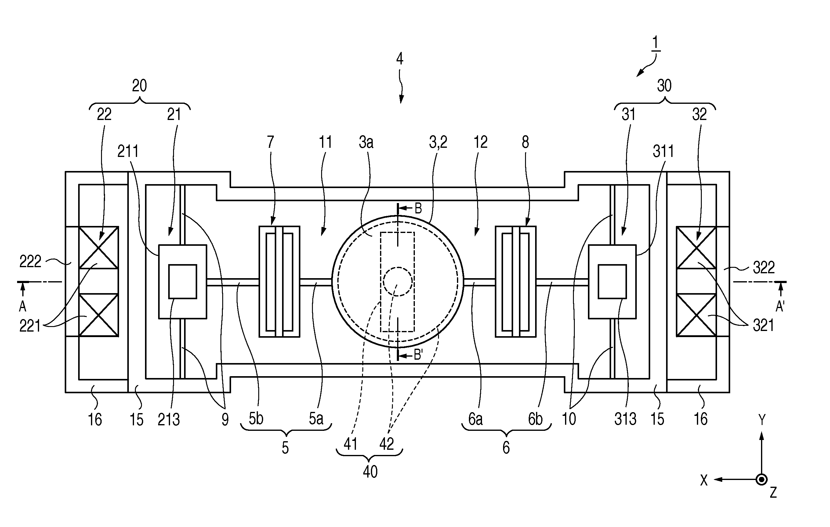
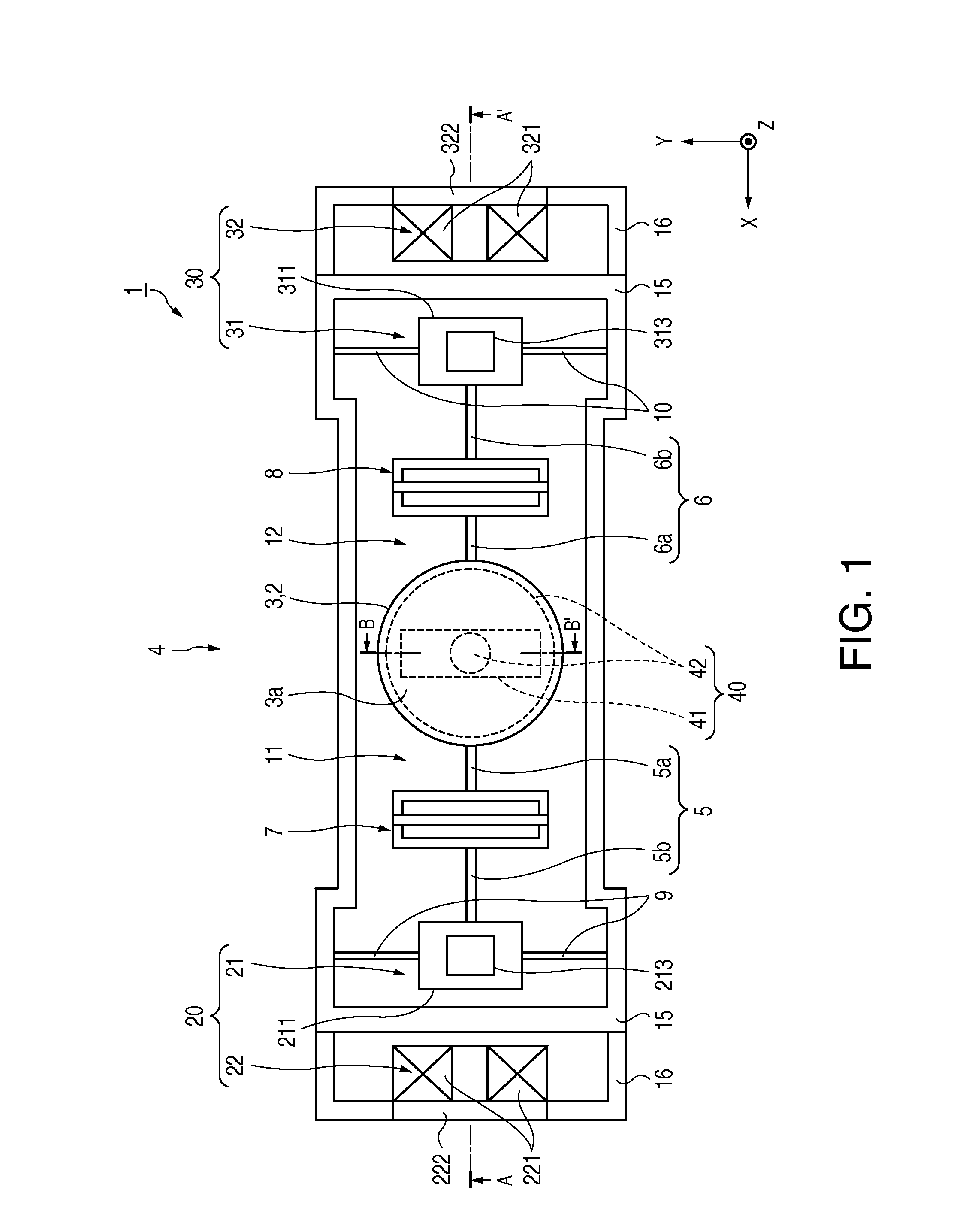
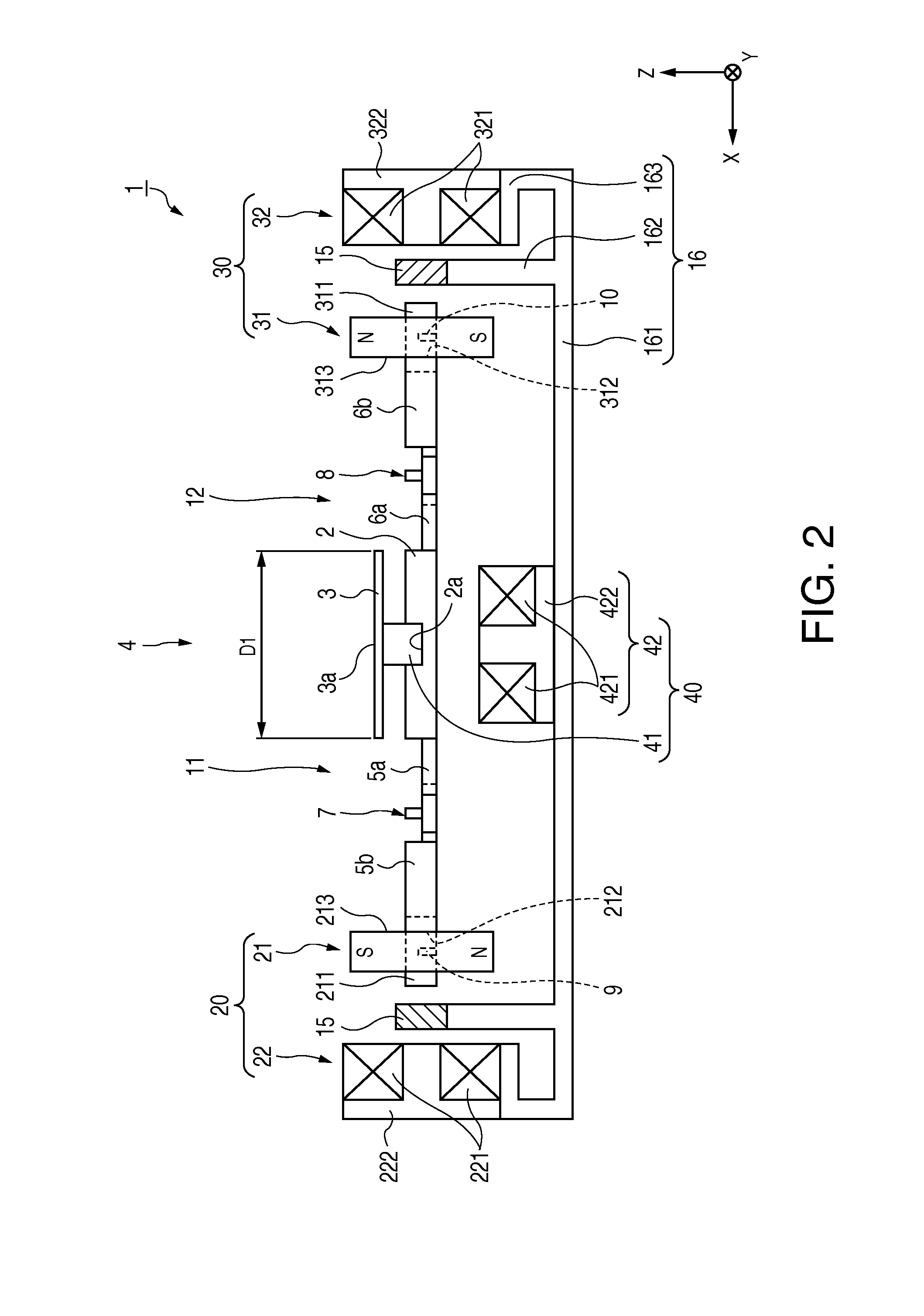
[0042]FIG. 1 is a plan view showing a configuration of a light scanner according to the embodiment of the invention. Further, FIG. 2 is a sectional view showing the configuration of the light scanner and shows a section along A-A′ of the light scanner shown in FIG. 1. Furthermore, FIG. 3 is a perspective view showing a movable beam and a drive unit for displacing a reflection plate. As shown in FIGS. 1 and 2, the light scanner 1 includes a movable part 2, two coupling parts 11, 12 connected to the movable part 2, first drive units 20, 30 provided on ends of the coupling parts 11, 12 at opposite sides to the movable part 2 for displacing the movable part 2 via the coupling parts 11, 12, a support frame 15 that supports the first drive units 20, 30, a base 16 that supports the support frame 15, and a second drive unit 40 for directly providing displacement different from those of the first drive units 20, 30 to the movable part 2. These movable part 2, coupling parts 11, 12, first dri...

modified example 1

[0082]The reflection plate 3 of the light scanner 1 has the circular shape having the diameter of D1 as approximation to the movable part 2, however, not limited to the configuration. The reflection plate may have a circular shape having a diameter D2 larger than that of the movable part 2 as long as the movable beams 5, 6 may function. FIG. 7A is a sectional view showing a modified example of the light scanner, and FIG. 7B is a sectional view showing driving of the first drive unit in the modified example. As shown in FIG. 7A, a reflection plate (light reflection member) 50 supported on the movable part 2 by the support member 41 has a light reflection surface 50a in an opposite direction to the movable part 2, and has a size such that its circumferential ends may reach displacement part-side beams 5b, 6b over the bending parts 7, 8. Even with the reflection plate 50 having the size, because the light reflection surface 50a is separated from the movable part 2 by the support member...

modified example 2

[0083]The support member 41 has a function of supporting the reflection plate 3 toward the movable part 2 and a function of displacing the movable part 2 as the second permanent magnet of the second drive unit 40, and these functions may be provided separately. FIG. 8 is a sectional view showing a modified example of the light scanner. As shown in FIG. 8, the reflection plate 3 is supported toward the movable part 2 by a support member 3b formed in a circular shape using silicon or the like, and the support member 41 as the second permanent magnet may have a configuration attached to the groove of an alignment guide 2b formed on the surface at the coil part 42 side of the movable part 2 for displacing the movable part 2 as a magnet. That is, the support member 41 specializes in the function as the second permanent magnet. Thereby, the support member 41 as the permanent magnet and the coil part 42 directly face each other, and thus, the second drive unit 40 produces displacement more...


PUM


Abstract

A light scanner includes a light reflection part having light reflectivity, a movable part having the light reflection part and being rotatable around a first rotation center axis and a second rotation center axis, a pair of movable beams extending from the movable part, a displacement part connected to the movable beams and rotating the movable part around the first rotation center axis, a first drive part that drives the displacement part, a pair of drive beams extending from the displacement part in parallel to the light reflection surface and orthogonal to an extension direction of the movable beams, a support frame that supports the drive beams, and a second drive part that rotates the movable part around the second rotation center axis, and the movable beam has a bending part that bendingly deforms due to displacement of the displacement part.

Description

BACKGROUND[0001]1. Technical Field[0002]The present invention relates to alight scanner for drawing or the like by light scanning, and an image forming apparatus including the light scanner.[0003]2. Related Art[0004]In related art, as disclosed in Patent Document 1 (JP-A-8-322227), an electromagnetic actuator having a function as a light scanner has been known. The electromagnetic actuator includes an insulating substrate on which a pair of permanent magnets are provided and a scanner main body located between the pair of permanent magnets and supported by the insulating substrate, and the scanner main body has the so-called gimbal structure having a frame-shaped support part, a frame-shaped outer movable plate provided inside of the support part, an inner movable plate with a total reflection mirror provided inside of the outer movable plate. Further, the outer movable plate is connected to the support part via a pair of first torsion bars, and the inner movable plate is connected ...

Claims


Application Information

Patent Timeline
IPC IPC(8): G02B26/08G02B26/10
CPCG02B26/085G02B26/101
Inventor WATANABE, EMIMIZOGUCHI, YASUSHI
Owner SEIKO EPSON CORP
Why Eureka
Try Eureka