
Method for separating seismic sources in marine seismic surveys

a technology of seismic survey and source separation, applied in seismology, seismic analysis of water-covered areas, instruments, etc., can solve the problems of interference reducing the bandwidth of recorded seismic signal, differences in acoustic impedance at the interface, etc., and achieve the effect of removing nois

Active Publication Date: 2012-02-16
PGS GEOPHYSICAL AS
View PDF7 Cites 14 Cited by
  • Summary
  • Abstract
  • Description
  • Claims
  • Application Information

AI Technical Summary

Problems solved by technology

Such seismic reflectors typically are interfaces between subterranean formations having different elastic properties, specifically sound wave velocity and rock density, which lead to differences in acoustic impedance at the interfaces.
This interference reduces the bandwidth of the recorded seismic signal.

Method used


Image

  • Method for separating seismic sources in marine seismic surveys
  • Method for separating seismic sources in marine seismic surveys
  • Method for separating seismic sources in marine seismic surveys

Examples


first embodiment

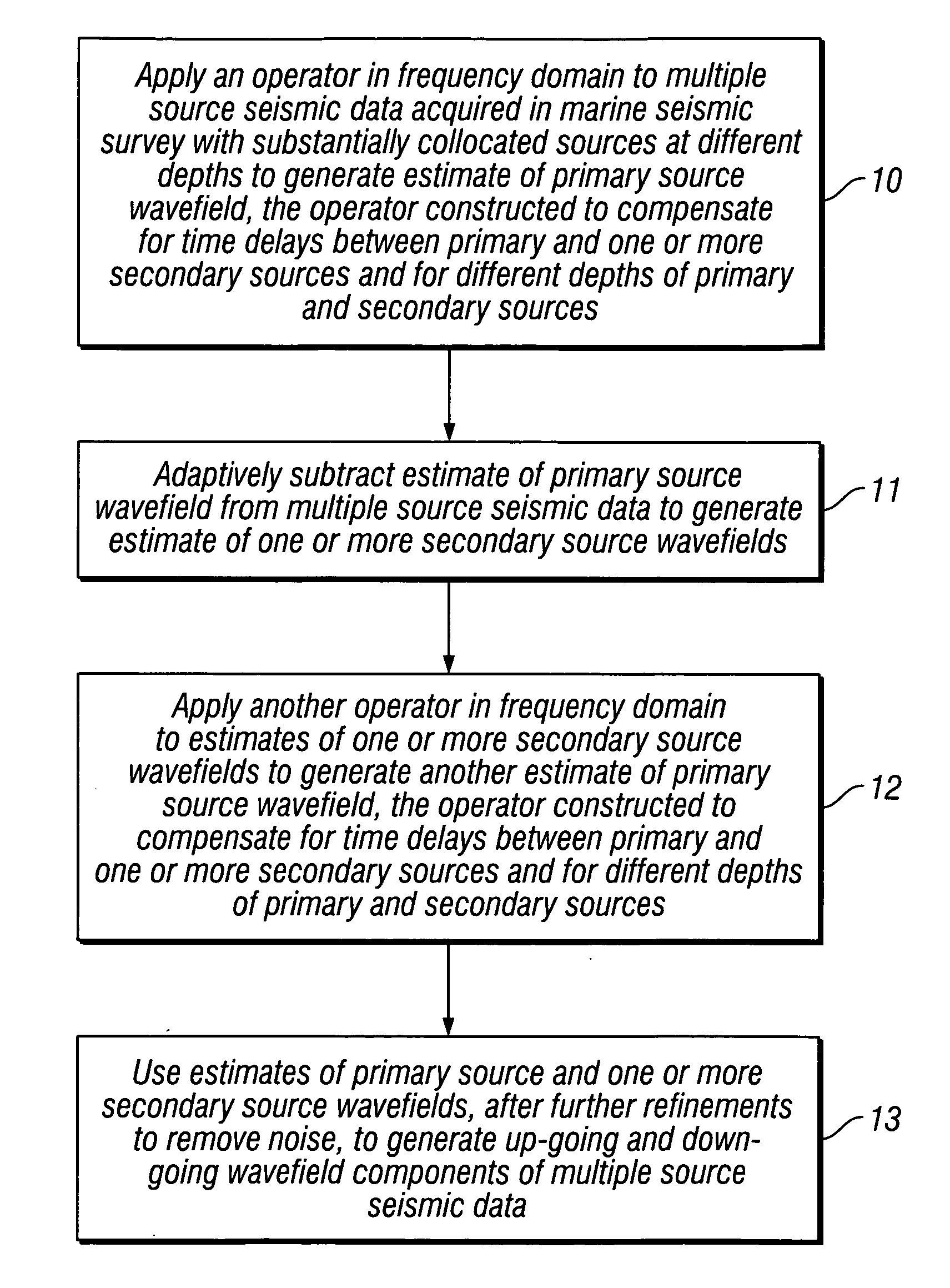
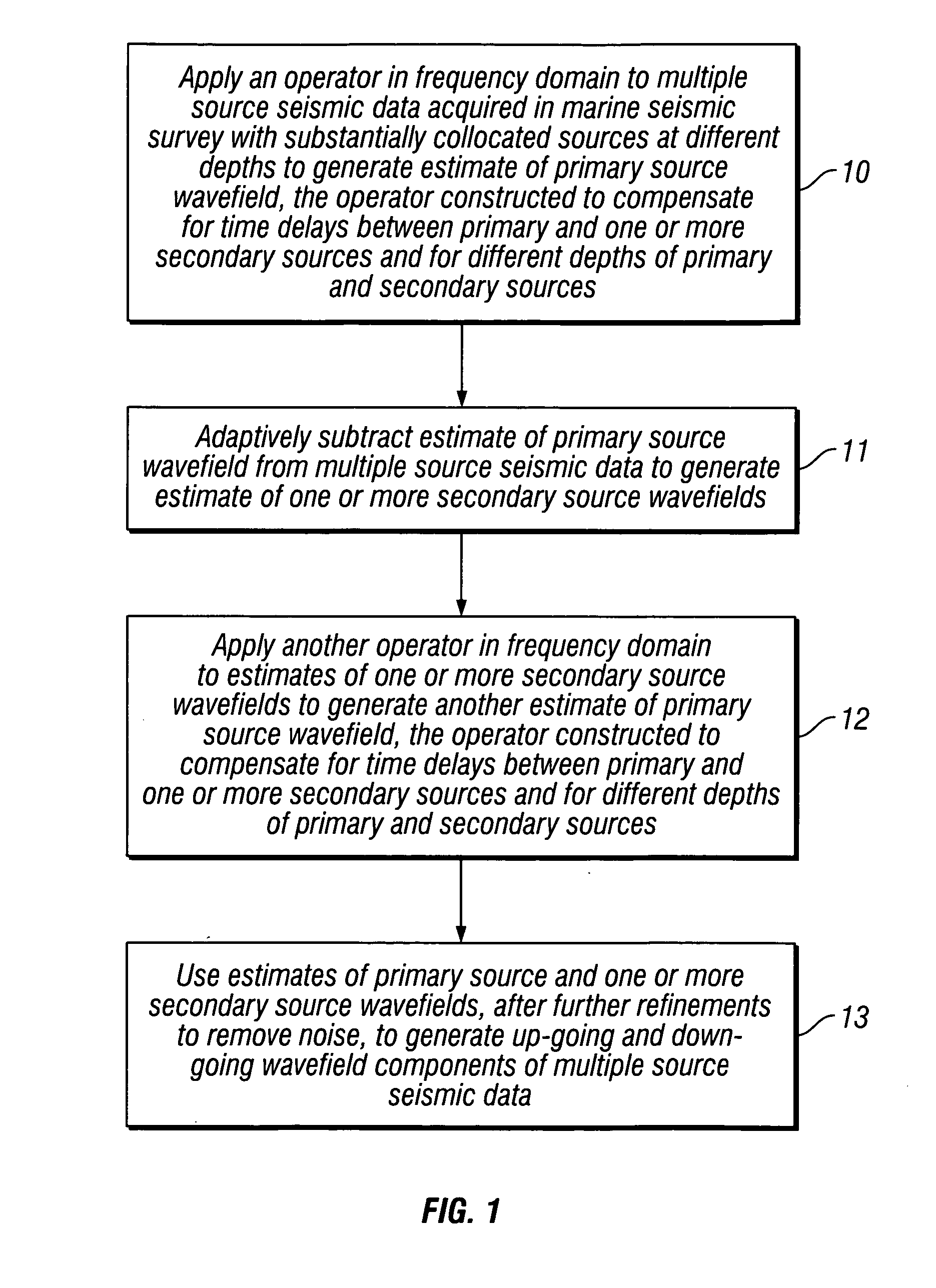
[0030]Once an estimate of the primary source wavefield has been obtained, this estimate can be refined. Two embodiments of the method for refining the primary source estimate will be presented here, but the method of the invention is not restricted to these two embodiments alone. In the first embodiment, the secondary source wavefield can be derived through (adaptive) subtraction of the estimated primary source wavefield from the original dual source measurement. After that, both estimates can be updated. In one embodiment, pre-conditioning is applied to the secondary source measurement to remove any unwanted noise. This estimate of the secondary source measurement is used to compute a new estimate of the primary source measurement by applying an operator to the estimate of the secondary source measurement, using Equation (11). This new estimate of the primary source measurement is then adaptively optimized again such that subtraction from the input data would lead to minimum energy...

second embodiment

[0031]In the second embodiment for refinement, the estimate of the primary source measurement and the estimate of the secondary source measurement are subtracted from the dual source measurement to generate a residual. The residual is given by:

{tilde over (R)}(sα1,sα2,x3S1,x3S2;s)={tilde over (P)}Dual(sα1,sα2,x3S1,x3S2;s)−{tilde over (P)}Primary(sα1,sα2,x3S1;s)−{tilde over (P)}Secondary(sα1,sα2,x3S2;s).   (12)

[0032]Then, the process starts again and the new residual estimate from the next iteration is added to the previous iteration results. In particular, the two embodiments use the operators described above.

[0033]The method of the invention applies to multiple source seismic data, not just dual source seismic data, as illustrated above for purposes of showing the principles clearly. The method of the invention applies equally to one or more secondary sources. Thus, there can be, in general, N-1 secondary sources positioned at depths x3=x3Sm, for m=2, 3, N, with corresponding wavef...


PUM


Abstract

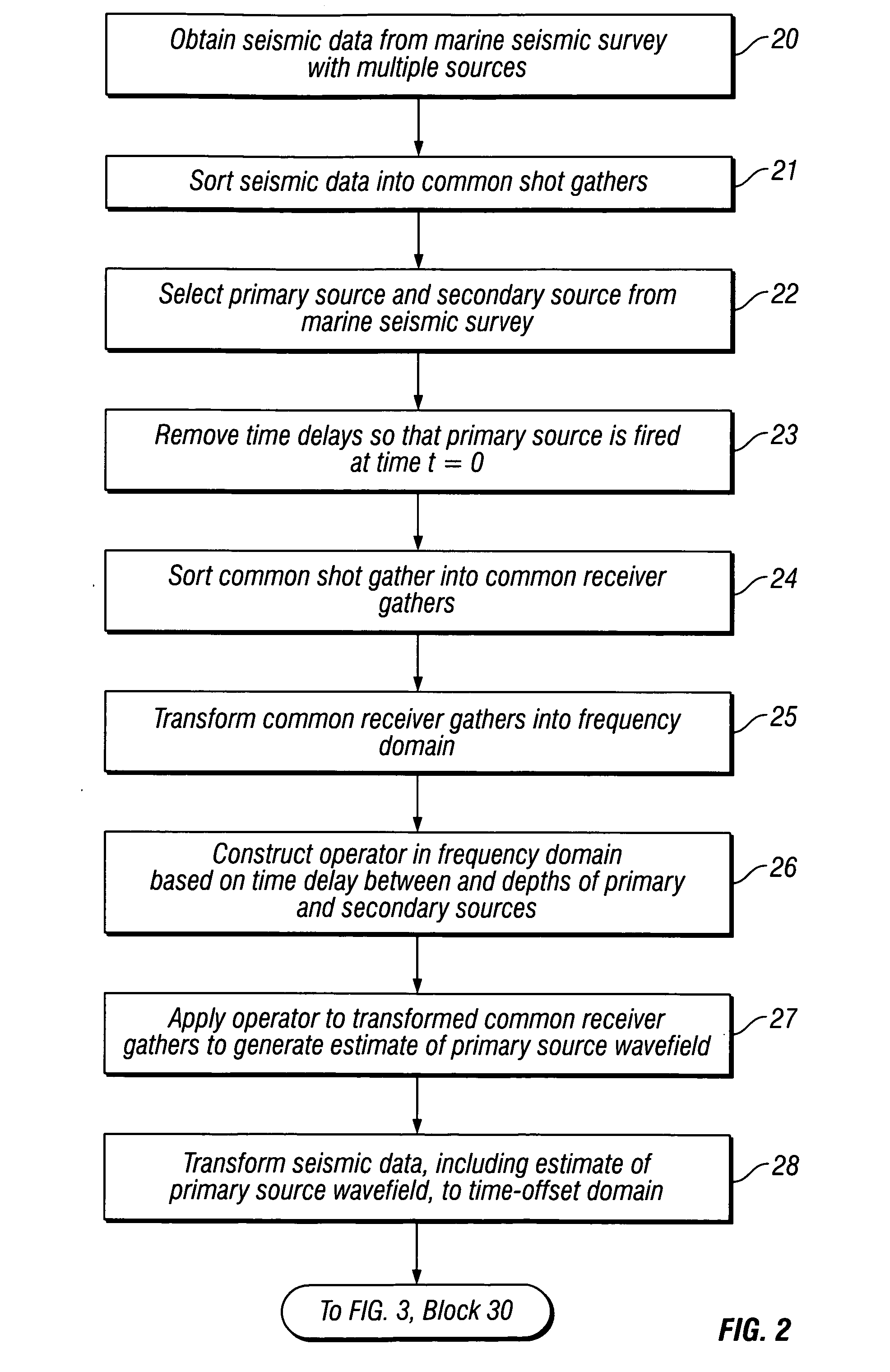
An operator is applied in a frequency domain to multiple source seismic data acquired in a marine survey, with multiple sources substantially horizontally collocated and at different depths, to generate an estimate of a primary source wavefield, the operator constructed to compensate for time delays between and for different depths of the primary and secondary sources. The primary source wavefield estimate is adaptively subtracted from the multiple source seismic data to generate secondary source wavefield estimates. Another operator is applied in the frequency domain to the secondary source wavefield estimates to generate another primary source wavefield estimate, the operator constructed to compensate for time delays between and for different depths of the primary and secondary sources. The primary and secondary source estimates are used, after further iterative refinements to remove noise, to generate upgoing and downgoing wavefield components of the multiple source seismic data.

Description

BACKGROUND OF THE INVENTION[0001]1. Field of the Invention[0002]This invention relates generally to the field of geophysical prospecting. More particularly, the invention relates to the field of imaging marine seismic streamer data.[0003]2. Description of the Related Art[0004]In the oil and gas industry, geophysical prospecting is commonly used to aid in the search for and evaluation of subsurface earth formations. Geophysical prospecting techniques yield knowledge of the subsurface structure of the earth, which is useful for finding and extracting valuable mineral resources, particularly hydrocarbon deposits such as oil and natural gas. A well-known technique of geophysical prospecting is a seismic survey. In a land-based seismic survey, a seismic signal is generated on or near the earth's surface and then travels downward into the subsurface of the earth. In a marine seismic survey, the seismic signal may also travel downward through a body of water overlying the subsurface of the...

Claims


Application Information

Patent Timeline
Patent Type & Authority Applications(United States)
IPC IPC(8): G01V1/38
CPCG01V1/362G01V2210/32G01V2210/40G01V1/364
Inventor VAN BORSELEN, ROALD G.HEGGE, ROBERTUS F.
Owner PGS GEOPHYSICAL AS
Learn More