Camera module

a camera module and camera technology, applied in the field of image capture, can solve the problems of affecting image quality, prone to displacement of camera modules, and increasing air pressure of interspace,

Active Publication Date: 2012-02-16
POLIGHT TECH LTD
View PDF6 Cites 11 Cited by
  • Summary
  • Abstract
  • Description
  • Claims
  • Application Information

AI Technical Summary

Problems solved by technology

However, the camera module is isolated from the ambient environment, and air pressure of the interspace can increase with increased temperature of the camera module during use.
As a result, components of the camera module are prone to displacement, with image quality affected accordingly.

Method used


Image

  • Camera module
  • Camera module
  • Camera module

Examples


Embodiment Construction

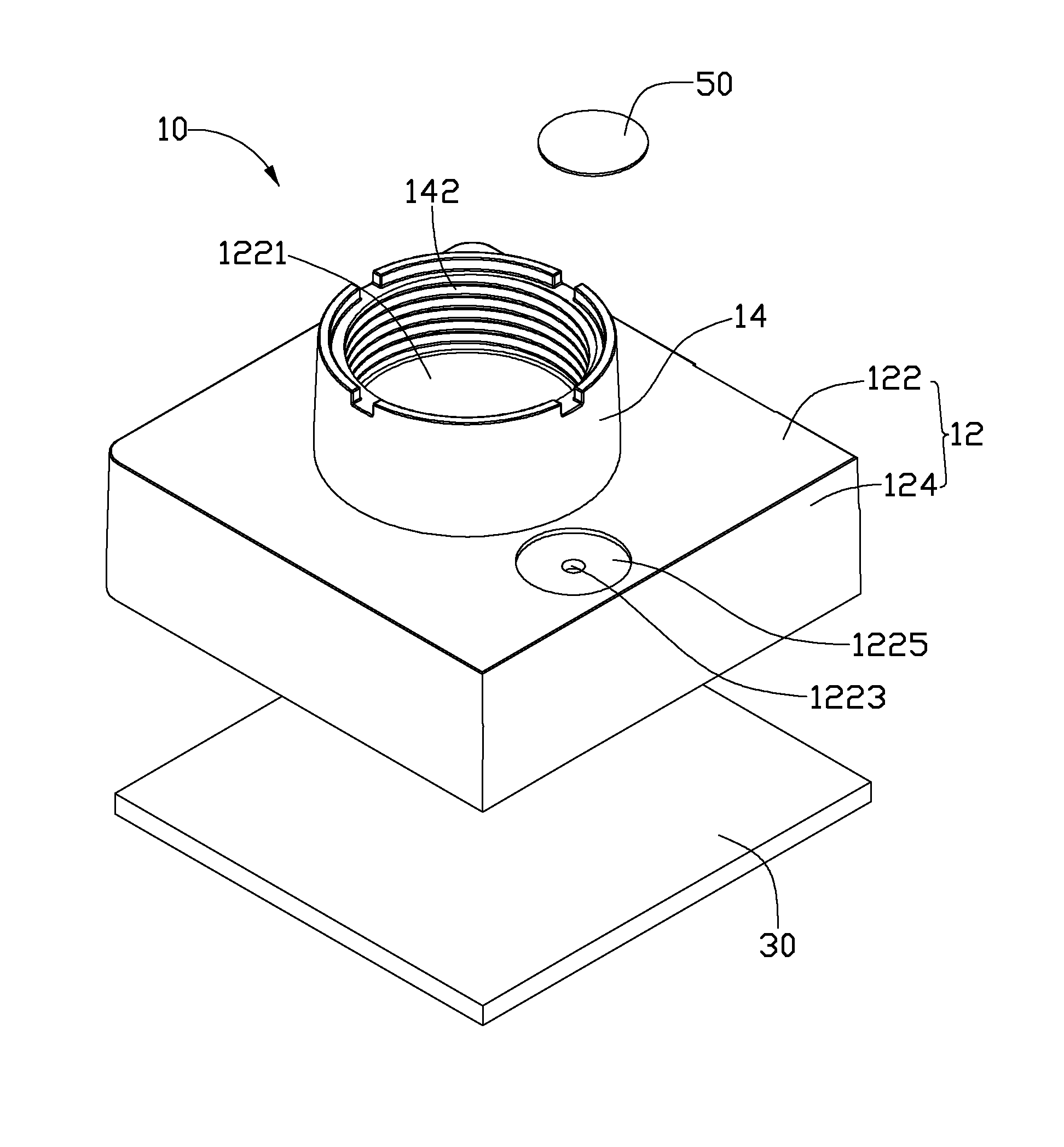
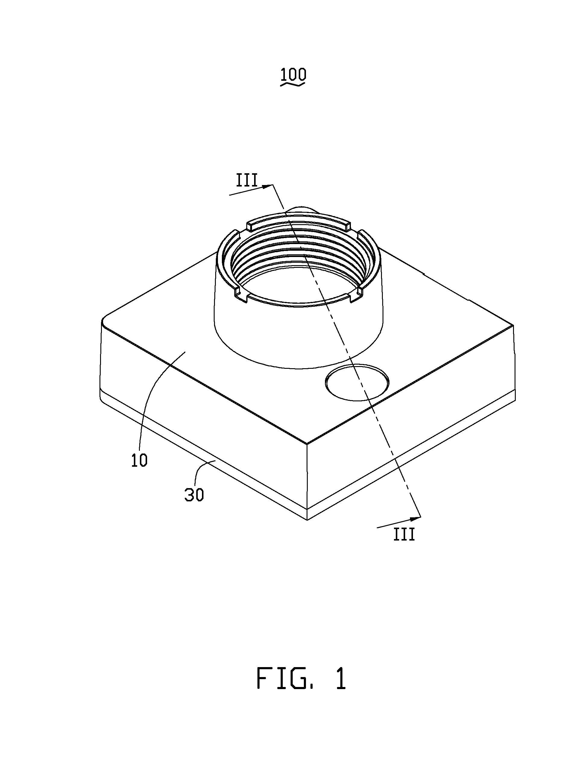
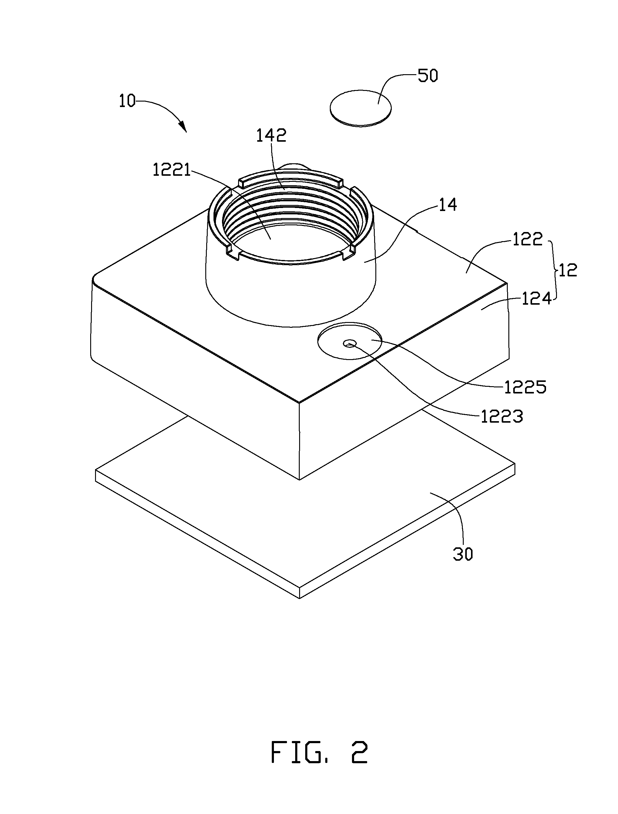
[0014]Referring to FIG. 1 and FIG. 2, a first embodiment of a camera module 100 includes a holder 10, a substrate 30, and a dustproof member 50. The holder 10 is mounted on the substrate 30.

[0015]Referring also to FIG. 3, the holder 10 includes a receiving portion 12, a mounting portion 14, and a reinforcing portion 18. The receiving portion 12 includes a support board 122 and a plurality of sidewalls 124. The support board 122 can be substantially rectangular. The receiving portion 122 includes four sidewalls 124 extending from four edges of the support board 122. The support board 122 defines a through hole 1221 corresponding to the mounting portion 14, and an air vent 1223. The through hole 1221 is substantially defined at a center of the support board 122. The support board 122 further defines a receiving groove 1225 depressed from the support board 122. The air vent 1223 is defined at a bottom surface of the receiving groove 1225 adjacent to the through hole 1221, and penetrate...


PUM


Abstract

A camera module includes a substrate, a holder, and a dustproof member. The holder is mounted on the substrate. The holder also defines an air vent. The dustproof member includes a permeable portion. The permeable portion is made of air-permeable material. The permeable portion shields the air vent. The dustproof member can also be made of a porous material plugging the air vent.

Description

BACKGROUND[0001]1.Technical Field[0002]The present disclosure relates to image capture, and more particularly, to a camera module used for an electronic device.[0003]2. Description of Related Art[0004]Camera modules are widely used in electronic devices such as personal digital assistants, mobile phones, portable computers, and other image capturing devices.[0005]A typical cameral module includes a substrate, a holder, and a lens barrel received in the holder. The holder defines an air vent. The holder is mounted on the substrate by thermoplastic adhesive bond film, and the pressure of an interspace defined between the holder and the substrate is regulated by the air vent during assembly of the holder and the substrate. After the assembly of the holder and the substrate, the air vent is sealed with glue, such as epoxy, to keep dust particles out.[0006]However, the camera module is isolated from the ambient environment, and air pressure of the interspace can increase with increased t...

Claims


Application Information

Patent Timeline
Patent Type & Authority Applications(United States)
IPC IPC(8): G03B17/02
CPCG02B27/0006H04N5/2257G03B17/12H04N23/57
Inventor HOU, SHENG-HUNGTUNG, YEN-LIANG
Owner POLIGHT TECH LTD
Why Eureka
Try Eureka