
Dual Panel Window Shade Apparatus with Improved Bottom Weight Bar and Rail

a dual-panel, window shade technology, applied in the direction of door/window protective devices, shutters/movable grilles, constructions, etc., can solve the problems of shade panels that wear out from added friction, tietig and morrison patent does not disclose a bottom weight bar or rail assembly

Inactive Publication Date: 2012-02-23
GASKILL ROBERT D +1
View PDF6 Cites 70 Cited by
  • Summary
  • Abstract
  • Description
  • Claims
  • Application Information

AI Technical Summary

Benefits of technology

[0011]When the shade panels are rotated simultaneously around the spool, the weight bar and its associated rail assembly rise with the bight formed at the bottom of the two panels. During this operation, the weight bar does not rotate, and there is no wear to the panel material caused by the weight bar. When the spool is rotated incrementally to adjust one of the panels relative to the other and vary the light passing through the dual panel shade, the weight bar rotates only a relatively small amount in the bight. The surface of the weight bar slides across the inner surface of the panel fabric only a minimal amount, thereby causing no or minimal wear of the panel material.

Problems solved by technology

The Morrison patent does not disclose a bottom weight bar in a housing or rail assembly that applies different tension forces on the shade panels when the shade panels are lifted together as compared to when the shade panels are shifting vertical positions relative to each other.
The Tietig patent does not disclose a bottom weight bar or rail assembly nor a dual panel window shade comprising a single piece of shade material.
As one of the shade panels is rolled onto the moveable roller tube, the rod in the bight continually rotates, causing the shade panels to wear out from the added friction caused by the rotating rod.
Prior art window treatments are relatively complicated in construction and operation, and have the additional disadvantages discussed above.

Method used


Image

  • Dual Panel Window Shade Apparatus with Improved Bottom Weight Bar and Rail
  • Dual Panel Window Shade Apparatus with Improved Bottom Weight Bar and Rail
  • Dual Panel Window Shade Apparatus with Improved Bottom Weight Bar and Rail

Examples


Embodiment Construction

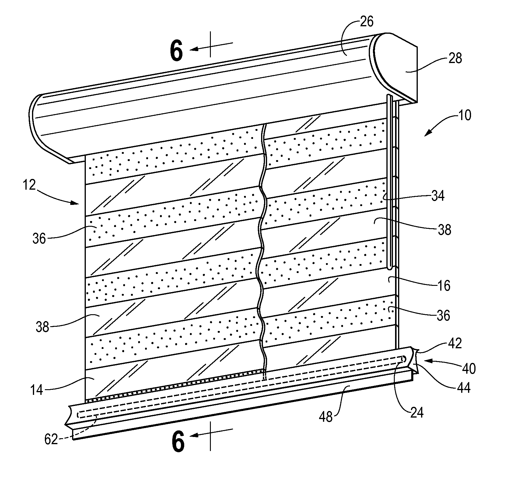
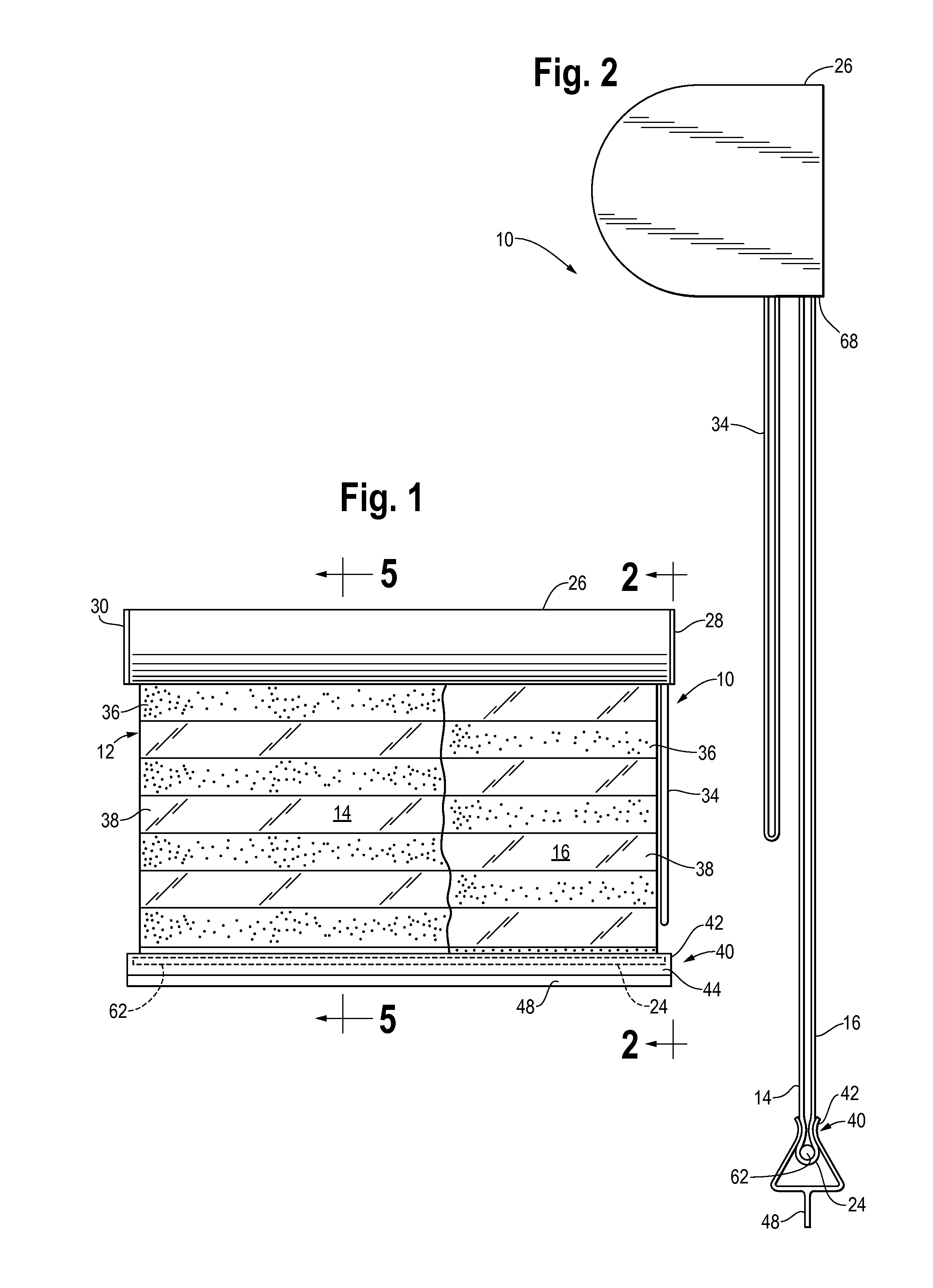
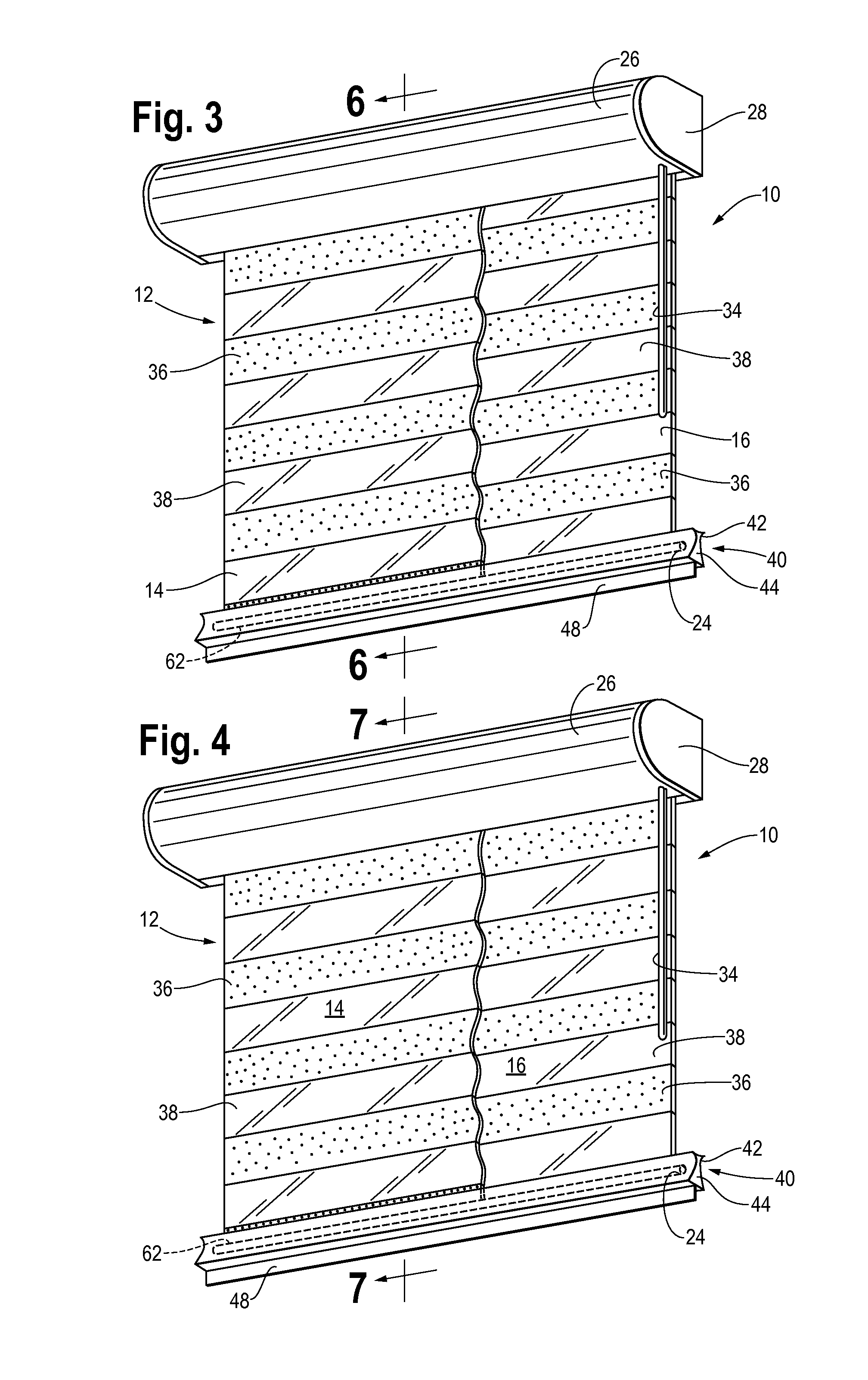
[0024]Referring to the drawings and FIGS. 1-7 in greater detail, the reference number 10 refers to a dual panel window shade apparatus. The shade apparatus 10 includes a single piece of material 12 formed in a loop and having a front panel 14 and a rear panel 16. As seen in FIG. 7, the upper portion of single piece of material 12 extends over and around the outer surface of spool or roller 18, and is fastened to spool 18 at two radially spaced apart locations, designated 20 and 22 in FIG. 7. At the bottom of shade material 12, panels 14 and 16 loop around to form a bight 24, as seen in FIGS. 8-10.

[0025]Referring to FIGS. 1-4, 7 and 11-12, the shade apparatus comprises a canopy 26 at the top of the apparatus. The canopy 26 is adapted to be fastened to a wall or sill over a window (not shown) as is known in the fastening art. The canopy includes opposed end flanges 28, 30. As shown in FIGS. 11 and 12, the ends of spool 18 are rotatably fastened to end flanges 28, 30 of canopy 26, such...


PUM


Abstract

A dual panel adjustable light transmission shade apparatus for adjusting the amount of light passing through a window comprises a spool rotatably mounted in a canopy, and an opening in the canopy. A single piece of material forms opposed facing front and rear panels, and a bight is formed at the bottom of the panels. An upper portion of each panel is fastened to the spool at spaced apart locations on the outer surface of the spool. One of the panels moves generally vertically upward and the other panel moves generally vertically downward when the spool is rotated in one direction. A weight bar is lodged in the bight at the bottom of the panels to apply a downward force on the panels, and the weight bar rotates in the bight only when the panels are adjusted relative to each other.

Description

FIELD OF THE INVENTION[0001]The present invention relates generally to window treatment apparatus, and more particularly to a vertically shifting dual panel roll-up window shade apparatus with an improved bottom weight bar and rail assembly to bring and hold the panel surfaces together as close as possible when the panels are extended.BACKGROUND OF THE INVENTION[0002]Window treatments are well known. In addition to aesthetic features, window treatments also provide privacy, protection from sunlight, and thermal insulation. U.S. Pat. No. 58,668 to Morris, discloses a double panel curtain window treatment, where a pair of panels, when extended, are spaced apart by a distance equal to the diameter of the upper roller to which each panel is attached. The two panels extend from the two different sides of the upper roller. Each separate panel is connected along bottom portions thereof by tacking to a bottom block. Each of the panels includes a series of aligned apertures. When the upper r...

Claims


Application Information

Patent Timeline
Patent Type & Authority Applications(United States)
IPC IPC(8): E06B9/44
CPCE06B9/42E06B2009/2447E06B2009/2405
Inventor GASKILL, ROBERT D.DISILVESTRO, ERNEST
Owner GASKILL ROBERT D
Learn More