Railway switch apparatus using dual comb structures

a switch apparatus and dual comb technology, applied in railway signalling, transportation and packaging, roads, etc., can solve the problem of design inherently unstable in the longitudinal axis

Active Publication Date: 2012-02-23
LANDOW HERBERT TRASK
View PDF1 Cites 4 Cited by
  • Summary
  • Abstract
  • Description
  • Claims
  • Application Information

AI Technical Summary

Benefits of technology

[0016]The lower comb moves in a horizontal plane and has upward facing teeth. The lower comb alternatively supports the raised upper comb and switch point or allo

Problems solved by technology

This makes the design inherently

Method used


Image

  • Railway switch apparatus using dual comb structures
  • Railway switch apparatus using dual comb structures
  • Railway switch apparatus using dual comb structures

Examples


Embodiment Construction

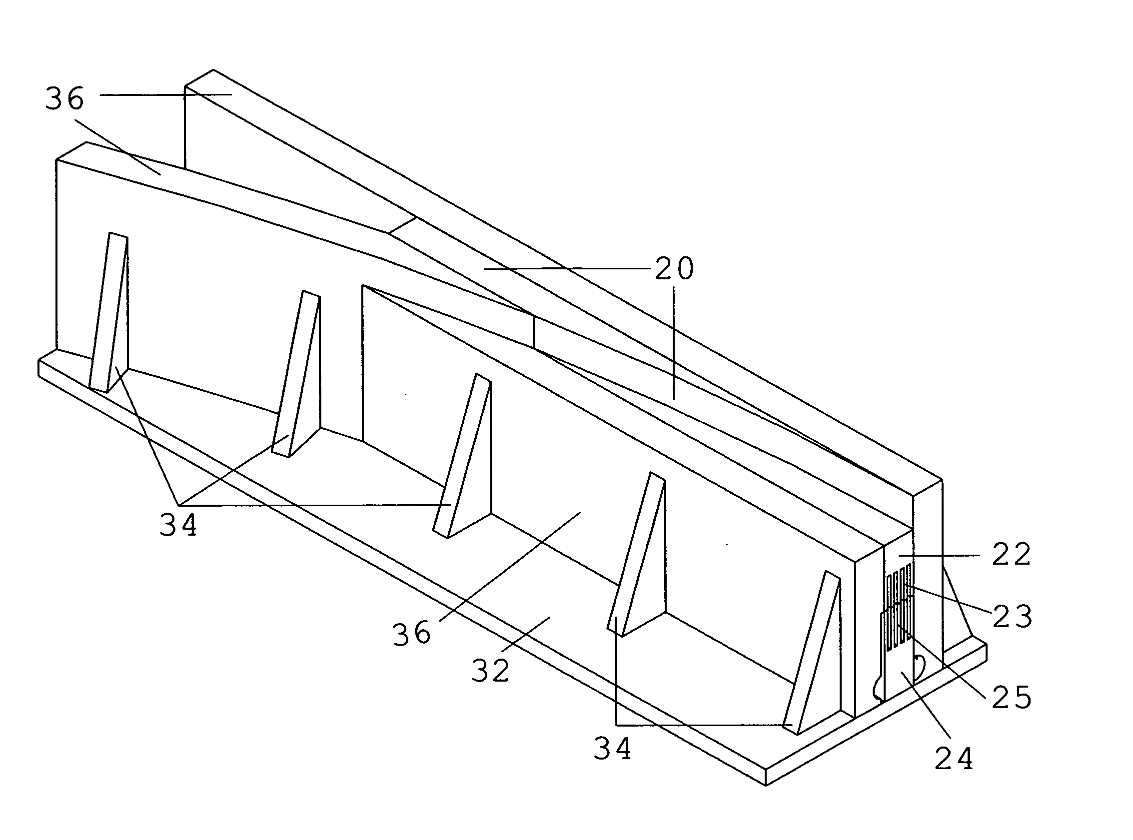
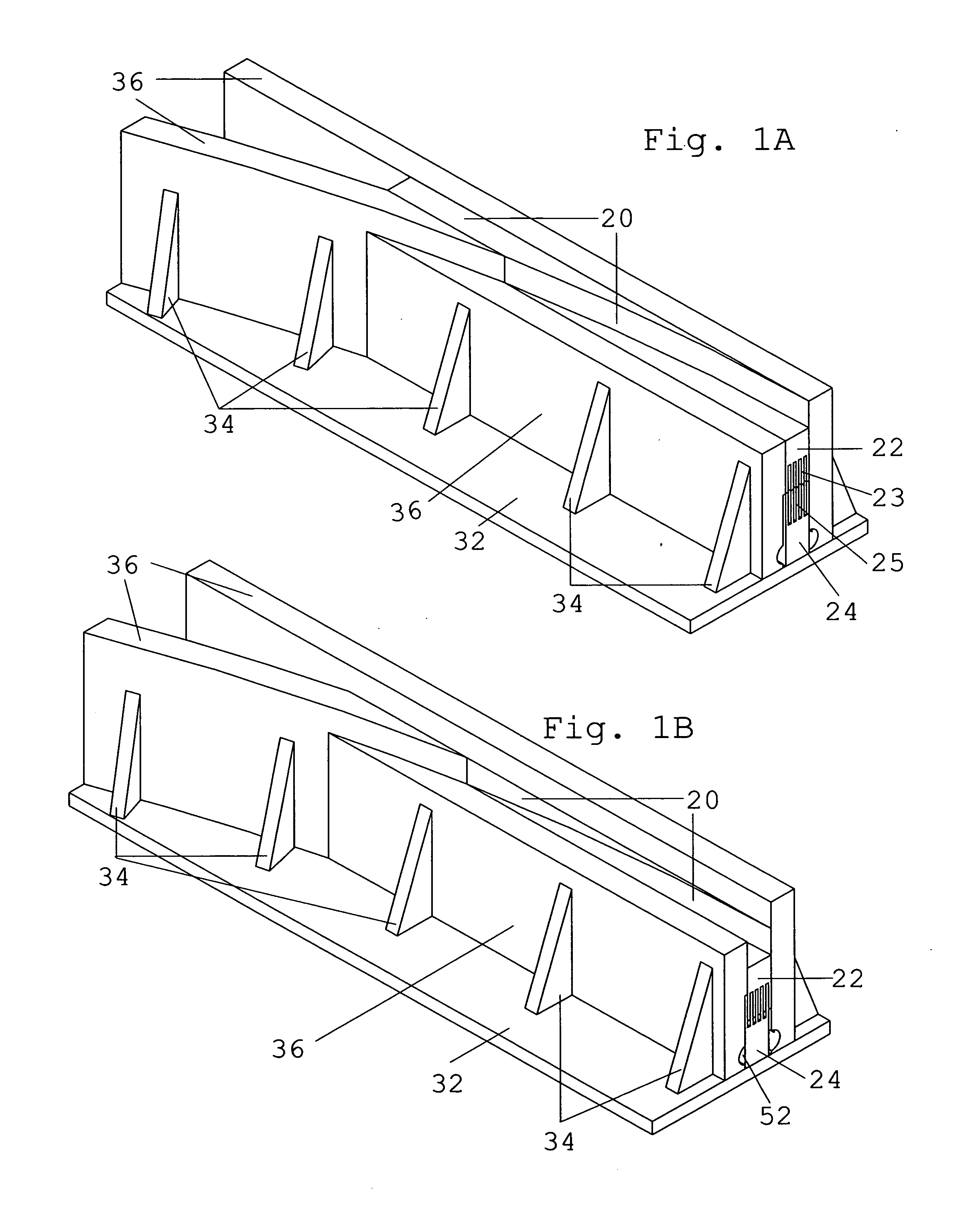
[0044]FIGS. 1A and 1B show the right side of a left hand turnout. FIG. 1A shows switch point 20 in an upper position to deflect a flange onto the curved route. FIG. 1B is the same as FIG. 1A but shows switch point 20 in the lowered position to allow the flange to follow the straight route.

[0045]Base plate 32 rests on the ties. Containment walls 36 and end plates 38 (not shown) encase the system making it a sealed unit except for the top working surfaces. Containment walls 36 are supported by braces 34.

[0046]Containment walls 36 act as running rails when their height is set at top of rail elevation. Some containment walls 36 have less elevation so as to allow the flange to pass overhead without contacting switch point 20. Switch point 20 rests on upper comb 22.

[0047]FIG. 1B shows comb structures 22, 24 nested together, positioning switch point 20 in the downward position.

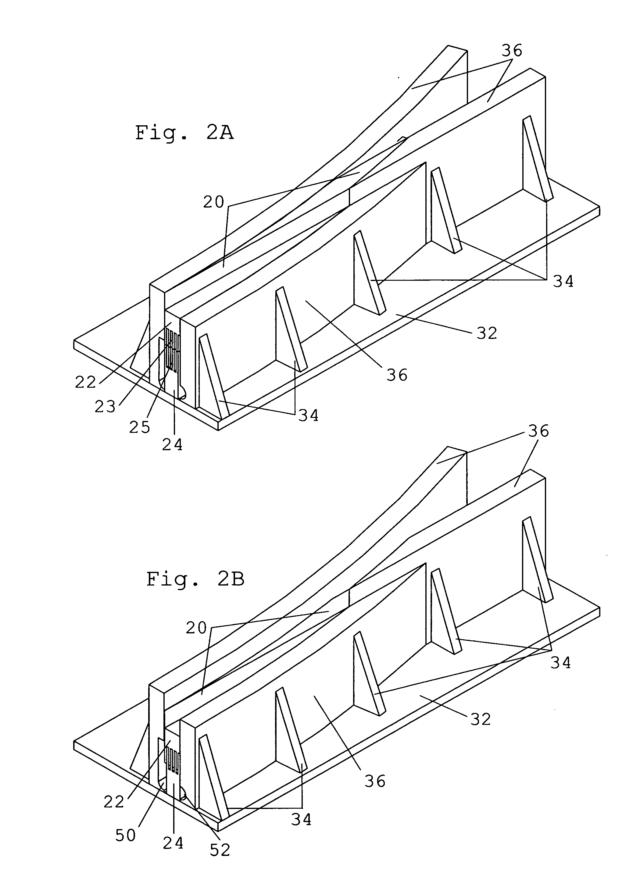
[0048]FIGS. 2A and 2B show the left side of a left hand turnout. FIG. 2A shows switch point 20 in an upper positio...


PUM


Abstract

A switch point (20) is alternatively raised and lowered. An upper comb structure (22) has a switch point (20) on its upper surface and teeth (23) on a lower surface. A lower comb structure (24) has compatible teeth (25) on its upper surface. The upper comb (22) moves only vertically. The lower comb structure (24) moves only horizontally. The combs may assume a raised configuration wherein the upper comb teeth (23) are supported on the lower comb teeth (25), or alternatively, a lowered configuration wherein the upper and lower comb teeth are nested. The comb structures (22, 24) have either laterally or longitudinally disposed teeth, and may be either linear or curvilinear with respect to a longitudinal axis. The combs and switch point are enveloped within containment walls (36) and end plates (38) so as to be a largely sealed unit.

Description

CROSS-REFERENCE TO RELATED APPLICATIONS [0001]Not ApplicableFEDERALLY SPONSORED RESEARCH [0002]Not ApplicableSEQUENCE LISTING OR PROGRAM [0003]Not ApplicableBACKGROUND [0004]1. Field of the Invention[0005]The invention pertains to vertically positioning railway switch points by utilizing the motion of two interacting comb structures.[0006]2. Prior Art[0007]For over 150 years switch points have moved by sliding in a horizontal plane. Throughout this long period innovation hopes have been focused on moving the switch points in a vertical plane. The virtues of vertically moving switch points include avoidance of blockage of the movement by snow, ice and debris. However, none of these vertical motion patents have resulted in a practical design that has been implemented. The designs were too weak to withstand the weights and forces experienced during typical railway operation.[0008]In the United States, for example, weights per individual axle exceed 32 metric tons. In addition, tractive...

Claims


Application Information

Patent Timeline
IPC IPC(8): E01B7/00
CPCE01B7/00B61L5/02
Inventor LANDOW, HERBERT TRASK
Owner LANDOW HERBERT TRASK
Why Eureka
Try Eureka