Aerially Deployed Illumination System

a technology of illumination system and illumination system, which is applied in the direction of lighting support devices, landing aids, instruments, etc., can solve the problems of uav's generally having a relatively small payload capacity, and affecting the performance of uav's

Inactive Publication Date: 2012-02-23
JONES KENNETH R
View PDF3 Cites 119 Cited by
  • Summary
  • Abstract
  • Description
  • Claims
  • Application Information

AI Technical Summary

Benefits of technology

[0051]The present illumination system is operable to float, hover and / or circle over a target for a fairly extended period of time, and generate / project a rapidly moving beam (spot or line) of collimated light upon the target, thereby creating the illusion of a broad area of constant illumination upon the target via the phenomenon of persistence of vision. Such an illumination system is desirable for deployment on a UAV platform due to the lightweight and low power consumption characteristics of the light source and illumination control device relative to the area of illumination provided thereby.

Problems solved by technology

However, such UAV's generally have a fairly small payload capacity, due to their light weight and low fuel / power capability.
Thus, the capabilities of UAV's are fairly limited due to limitations in payload and range, the range thereof being dramatically impacted by increases in payload.
However, such lighting / illumination systems are heavy, and thus require a large UAV platform for deployment thereof.
Further, it is believed that such a system is manually operated, and has a limited range and time on station.
However, such laser designators are incapable of illuminating a wide area for visible viewing of a target.
Such apparatuses, however, are sophisticated, heavy, and consume large amounts of power, thus making them unsuitable for deployment on light weight UAV platforms.
Namely, the chemicals used therein (white phosphorous, cesium nitrate, etc.) are highly toxic and very dangerous, making handling and disposal difficult.
Further, they offer limited illumination time because they burn while rapidly falling to earth from a low altitude; illumination durations of approximately 50 seconds to less than two minutes are typical.
In addition, the residual projectile components of traditional illumination rounds are a hazard due to their mass and can cause serious unintentional damage when they eventually fall to earth.
Further, because the chemical light may still be burning when it strikes the ground, the burning chemical can initiate unintentional fires when landing on or near flammable material, which is a common occurrence.
Another byproduct of a descending light source, such as the traditional M816 illumination mortar, is that the area of illumination produced thereby is non-uniform.
In addition to the technical disadvantages of conventional illumination rounds, as discussed above, cost of the current rounds is a major factor when considering use thereof.
During a typical engagement, dozens to hundreds of illumination rounds may be employed, which is clearly very costly.

Method used


Image

  • Aerially Deployed Illumination System
  • Aerially Deployed Illumination System
  • Aerially Deployed Illumination System

Examples


Embodiment Construction

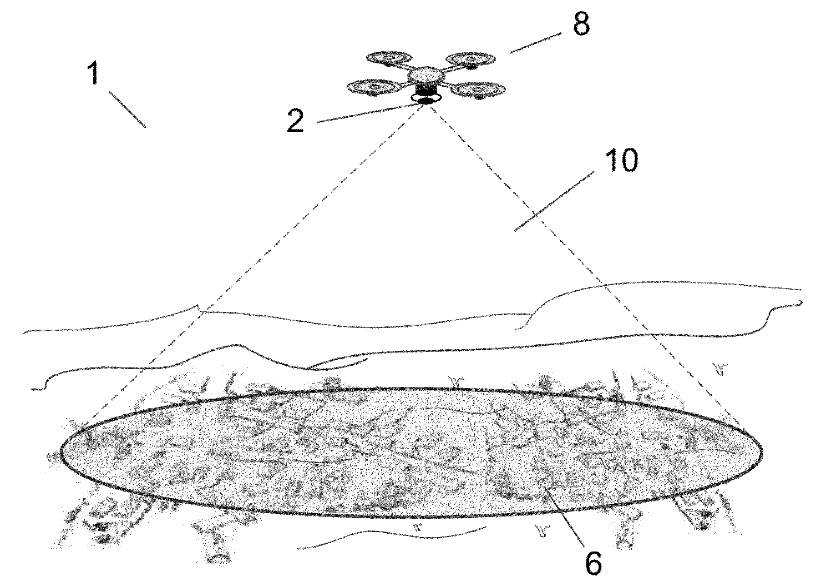
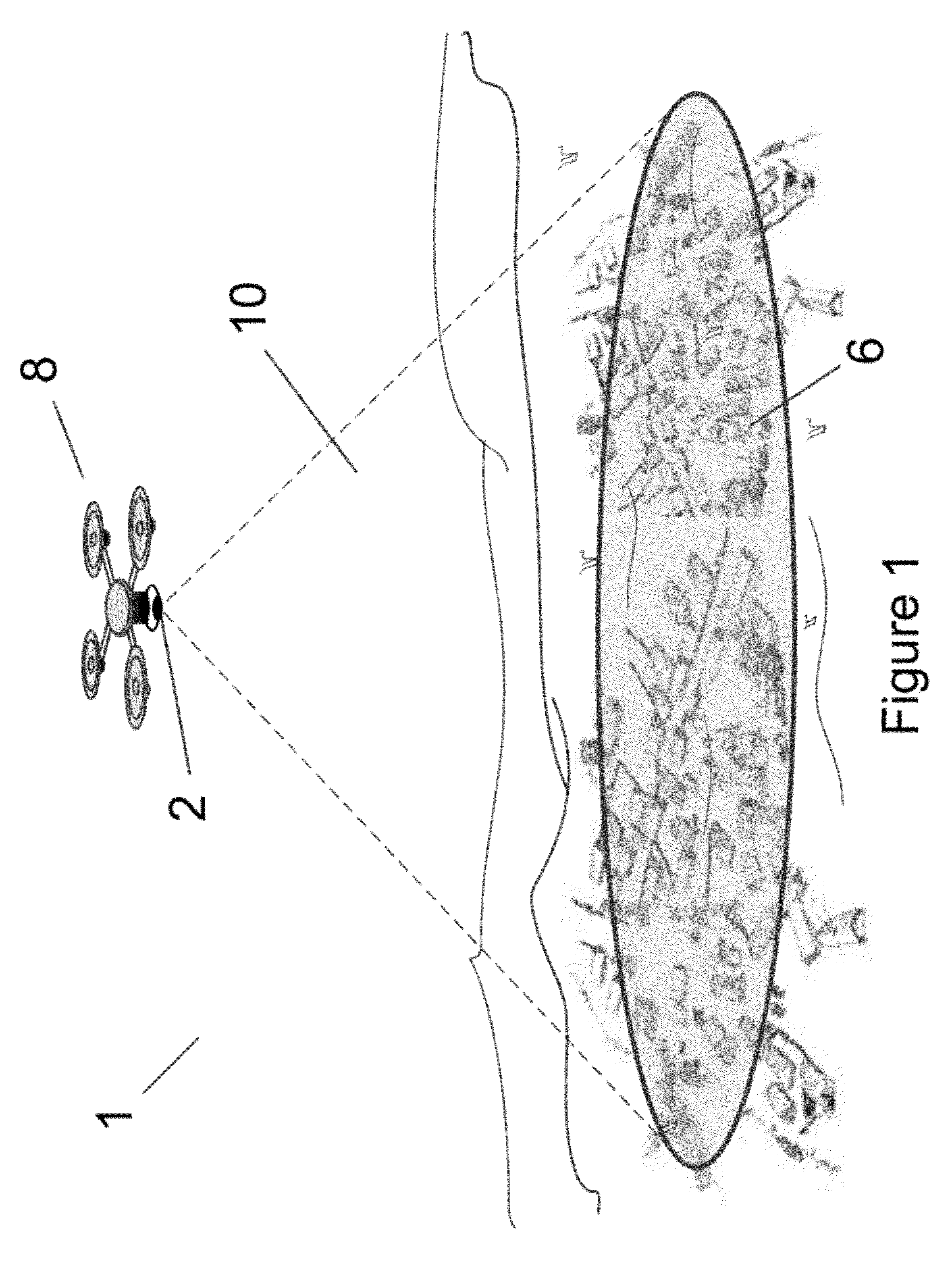
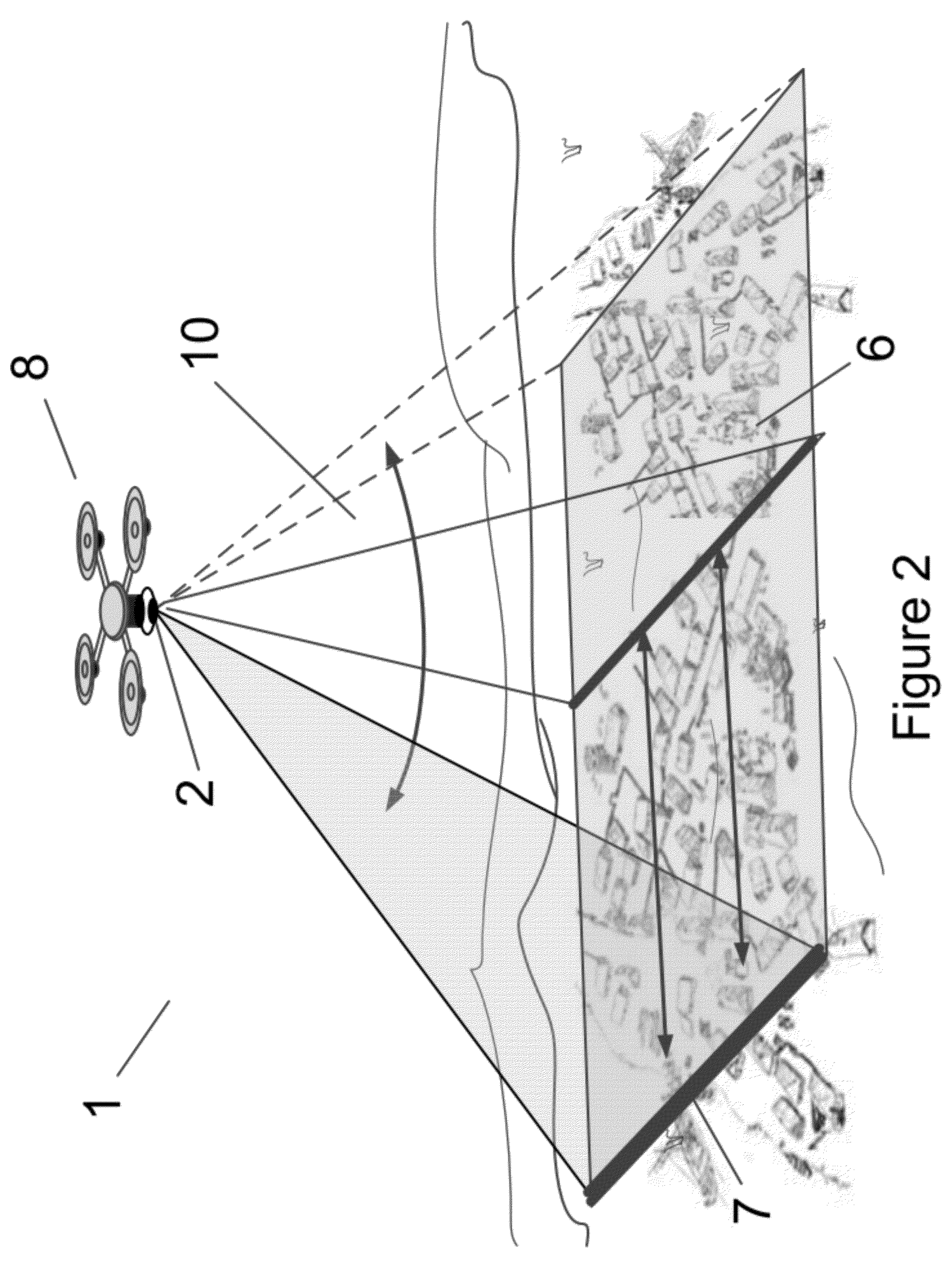
[0073]As mentioned above, generally, both gas and electric powered UAV's have a fairly low payload capacity. Thus, it is important that the UAV-deployed illumination system be lightweight and consume a low amount of power. However, it is equally important to provide a sufficient amount of illumination on a target for proper viewing thereof. Currently, no conventional aerially deployed methods of illumination provide these two characteristics, namely, low mass and high illumination power.

[0074]To cure these deficiencies, and provide an aerially deployed illumination means which can be disposed on a small UAV and is capable of illuminating a relatively large area, the present inventors have developed an aerially deployed illumination system comprised of one or more unmanned aerial vehicles (UAV's), each of same having an illumination system disposed thereon. In particular, as illustrated in FIG. 15, each UAV 1 is comprised of a central microprocessor 18; a wireless communication means...


PUM


Abstract

An aerially deployed illumination system is provided which may be remotely operated or preprogrammed to illuminate a designated target, such as a geographic area, vehicle, or personnel. In particular, a remotely controlled UAV having an illumination system disposed thereon is provided, the illumination system comprised of a concentrated light source and light movement apparatus operable to rapidly scan the target with the light source, thereby providing an illusion of a large area of illumination. Preferably, a line is created from the light source, the line being rapidly moved over the target in specific patterns and at specific frequencies. The system may further include a plurality of UAV's capable of ad hoc networking, so as to illuminate both large areas, as well as stationary and moving targets. In addition, the UAV's having an illumination system disposed thereon may be disposed within a projectile, the projectile tube or gun launched, and the UAV ejected from the projectile over a designated target, thereby enabling quick delivery of the UAV to an area of interest.

Description

REFERENCE TO RELATED APPLICATION[0001]This application is a non-provisional application corresponding to and claiming priority of prior filed U.S. provisional application Ser. No. 61 / 374,591, filed Aug. 17, 2011, the contents of which is hereby incorporated by reference.BACKGROUND OF THE INVENTION[0002]1. Field of the Invention[0003]The present invention provides an aerially deployed illumination system which may be tube or gun launched, or deployed on an unmanned aerial vehicle (UAV), which may be remotely operated and / or preprogrammed to illuminate a designated geographic area, structure, vehicle or personnel. In particular, an unmanned aerial vehicle (UAV) deployed or tube / gun launched illumination system is provided, wherein a relatively light weight, low power, concentrated light source disposed on the UAV or launched from a land based platform such as a mortar tube, artillery gun, rocket launcher or tube launch system, is operable to illuminate an area via rapid scanning of th...

Claims


Application Information

Patent Timeline
Patent Type & Authority Applications(United States)
IPC IPC(8): B64C39/02
CPCB64C39/024B64C2201/027B64C2201/042F42B12/42B64C2201/123B64C2201/127B64C2201/108G05D1/0094B64U10/13B64U50/19B64U30/20B64U2101/30B64U2101/00
Inventor JONES, KENNETH R.
Owner JONES KENNETH R
Why Eureka
Try Eureka