Robotic Knee Testing Device, Subjective Patient Input Device and Methods for Using Same

a robot knee and knee technology, applied in the direction of application, radiation beam directing means, person identification, etc., can solve the problems of increasing or decreasing abnormal or pathological condition in the knee, and unable to quantify the increase or decrease in the ‘joint play’ or knee motion with limited success,

Active Publication Date: 2012-02-23
ERMI
View PDF14 Cites 83 Cited by
  • Summary
  • Abstract
  • Description
  • Claims
  • Application Information

AI Technical Summary

Problems solved by technology

When this ‘joint play’ is increased or decreased, an abnormal or pathological condition exists in the knee.
Attempts have been made in the past to quantify this increase or decrease in ‘joint play’ of the knee with limited success.
An injury to the knee can cause damage to one or more of the structures of the knee causing an increase in the ‘joint play’ or motion of the knee.
All of these tests suffer from the clinician's subjective evaluation of both the extent of the ligament lengthening and the change in the compliance or stretchiness of the ligament.
This test is difficult to perform, difficult to teach and difficult to quantify.
A misdiagnosis can lead to unnecessary delay in treatment, thereby placing the patient at increased risk for further damage to the knee.
The more ligaments and structures that are damaged; the more complex it becomes to perform a knee examination using the subjective manual exams.
One of these devices is The KT-1000 and the KT-2000 Medmetric®, which measures the anterior-posterior translation of the tibia with respect to the femur along the z-axis, but disadvantageously attach to the tibia.
This device does not measure relative displacement or compliance in any of the other degrees of freedom previously described in the knee.
These skin sensors or markers are merely representations of location of the underlying bones; however, many published reports have documents the measurement error related to skin artifact with this system.
Surgeons manually examine the joint for altered play; however, due to the variability in size of the patient, size and experience of the surgeon, and the subtlety of injury, consistent and reproducible reports of joint play between surgeons is not possible.
Many reports have documented that, whether performed by hand or with manual arthrometers, the manual application of torque varies between clinicians, thus creating inconsistencies in the examination of joint play.

Method used


Image

  • Robotic Knee Testing Device, Subjective Patient Input Device and Methods for Using Same
  • Robotic Knee Testing Device, Subjective Patient Input Device and Methods for Using Same
  • Robotic Knee Testing Device, Subjective Patient Input Device and Methods for Using Same

Examples


Embodiment Construction

I. General Overview

[0070]The present inventions now will be described more fully hereinafter with reference to the accompanying drawings, in which some, but not all embodiments of the inventions are shown. Indeed, these inventions may be embodied in many different forms and should not be construed as limited to the embodiments set forth herein; rather, these embodiments are provided so that this disclosure will satisfy applicable legal requirements. Like numbers refer to like elements throughout.

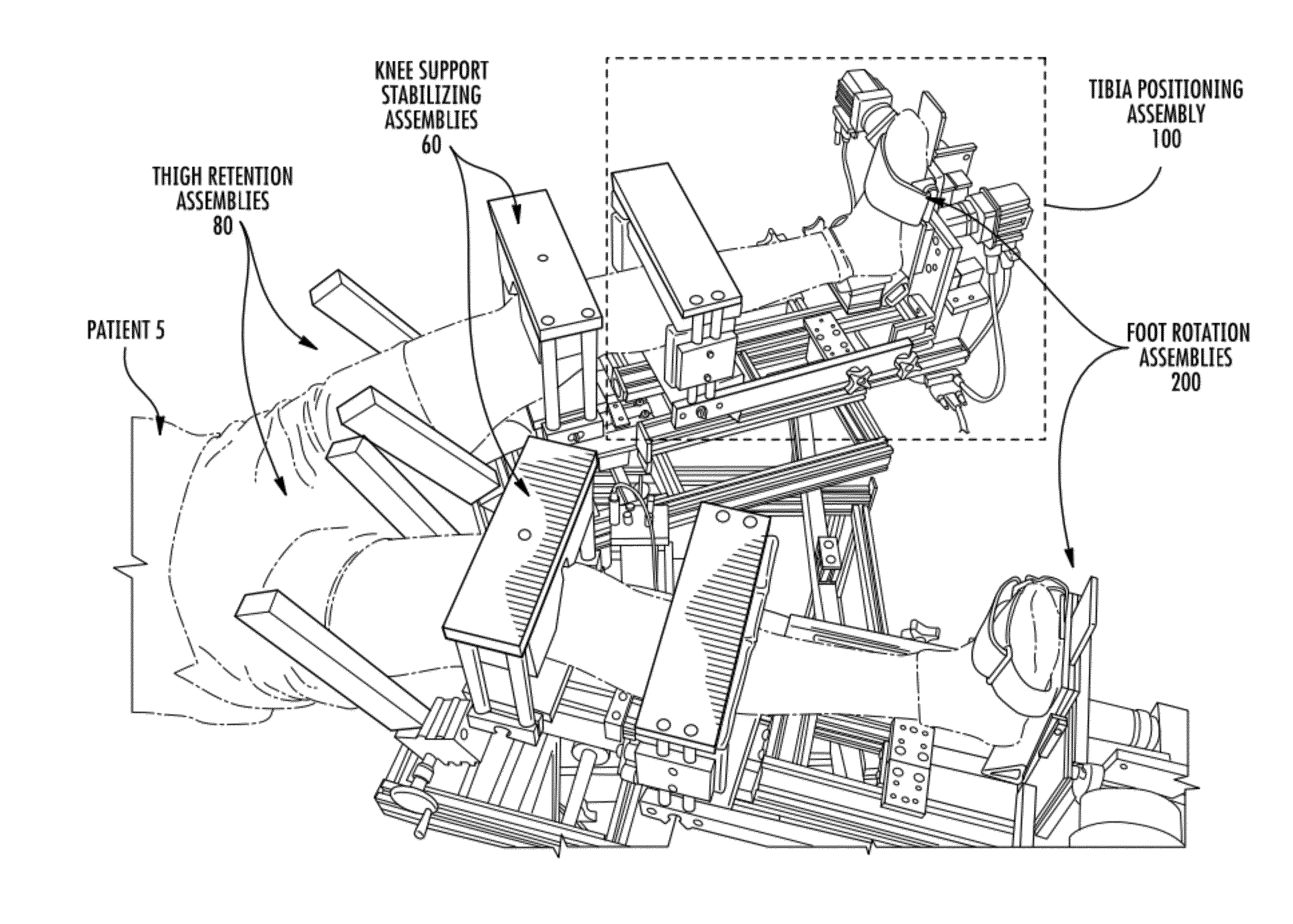
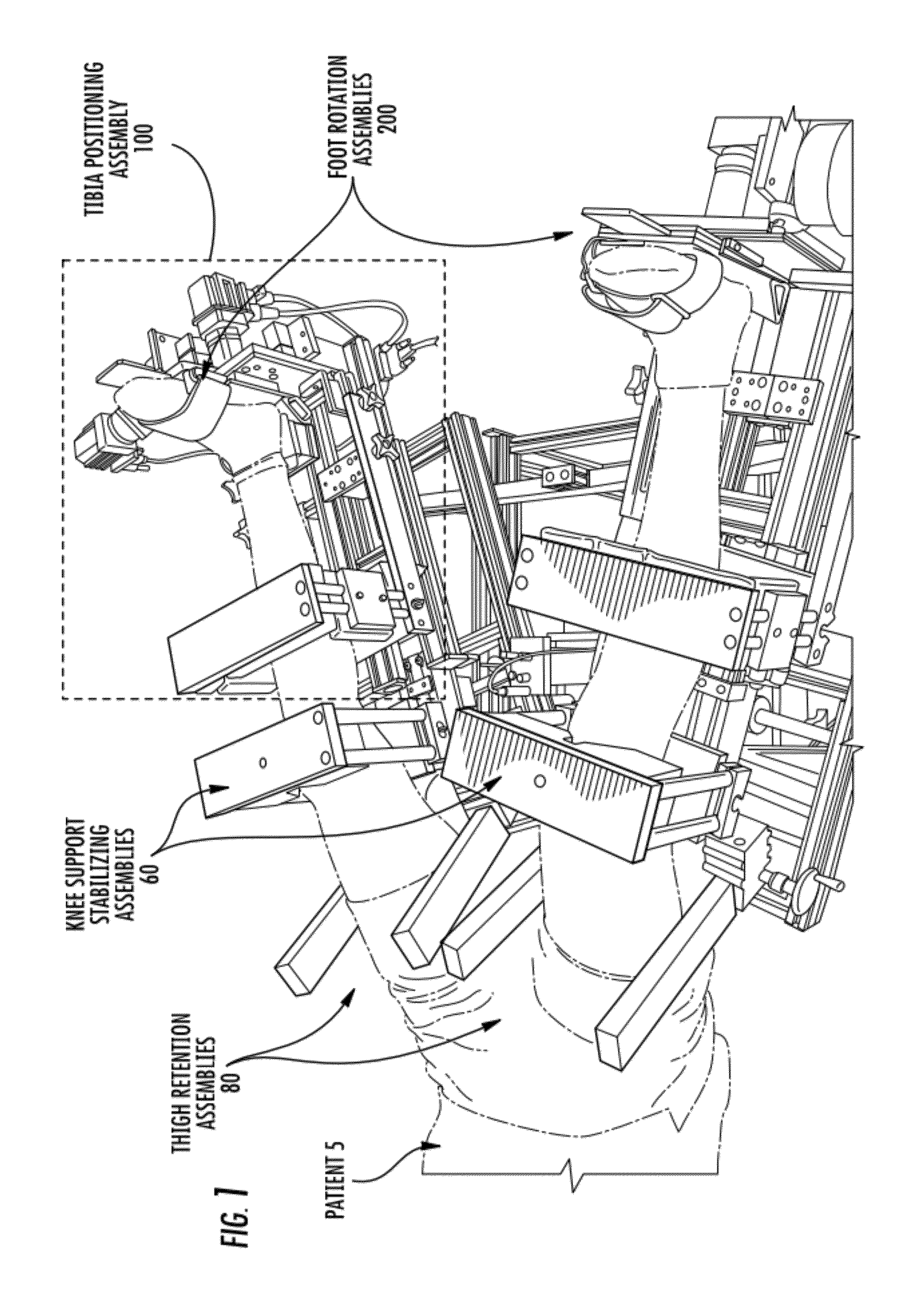
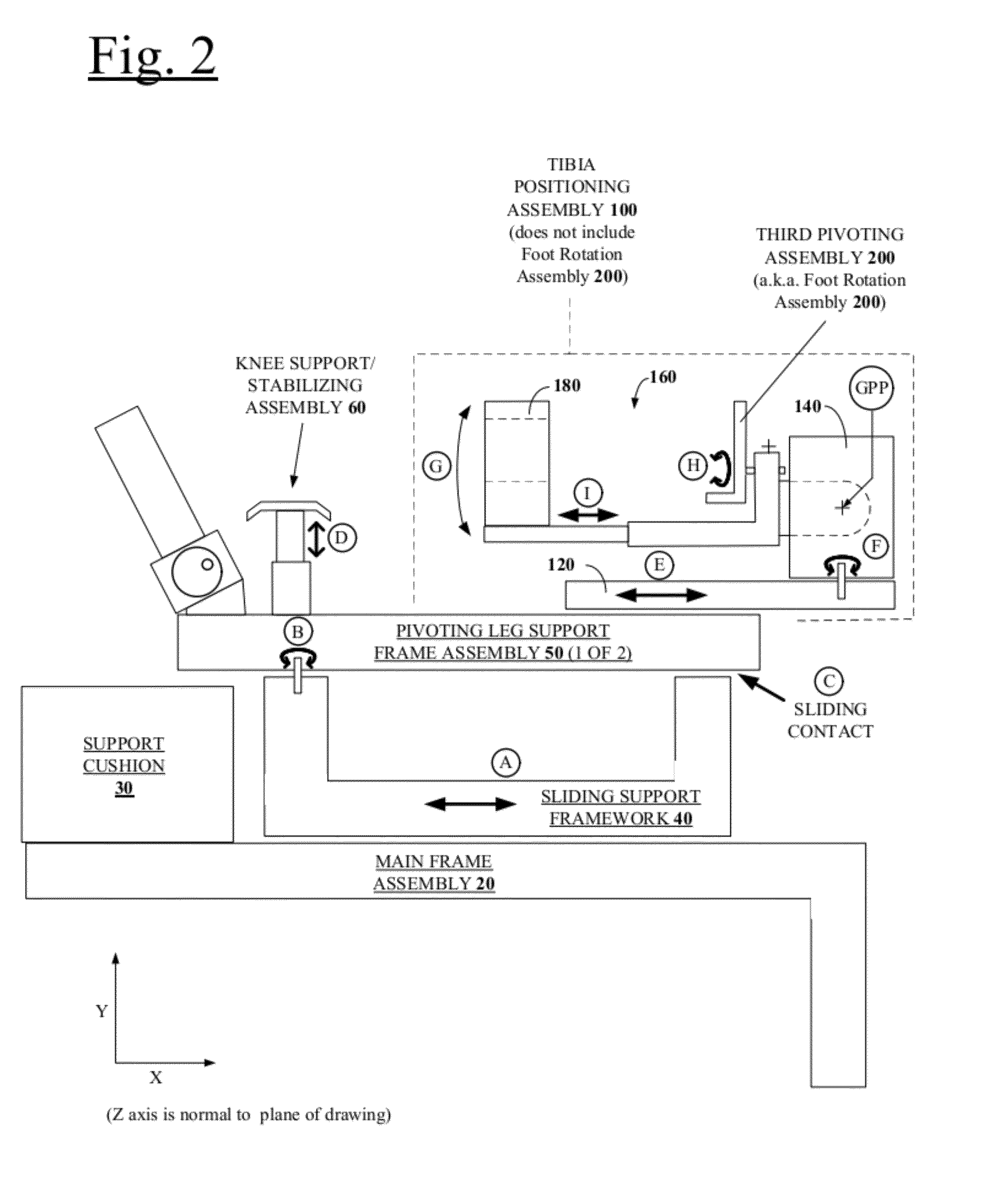
[0071]Generally described, various embodiments of the present invention provide robotically controlled devices and methods for evaluating the knee, although other joints and limbs can likewise be evaluated such as the elbow and arm. In one aspect of the invention, devices and methods are provided, which apply a known torque to the lower leg of a user and monitor the reaction to this torque at the knee. Such devices and methods may be generally configured to control the direction, rate, and m...


PUM


Abstract

An apparatus for evaluating leg movement characteristics of a patient is provided. The apparatus comprises a base assembly configured to at least partially support the patient's torso; and first and second leg support assemblies independently pivotably mounted about a pivot axis relative to the base assembly. Each leg support assembly is configured to at least partially support a portion of a respective one of the first and second legs, independent of the support of the torso. Each of the leg support assemblies also comprises: a first leg support member including a foot rotation assembly configured to at least partially retain and support an associated foot of the patient and to rotate it about an axis of rotation relative to the base assembly; and a second leg support member configured for supporting a portion of the leg at a location proximal relative to the first leg support member.

Description

CROSS-REFERENCE TO RELATED APPLICATIONS[0001]This application claims priority to and the benefit of U.S. Provisional Application No. 61 / 373,643, filed Aug. 13, 2010, entitled “Robotic Knee Testing Device, Subjective Patient Input Device, and Method for Using the Same,” U.S. Provisional Application No. 61 / 377,688, filed Aug. 27, 2010, entitled “Robotic Knee Testing Device, Subjective Patient Input Device, Bladder Driven Linear Actuator, and Methods for Using the Same,” and U.S. Provisional Application No. 61 / 513,926, filed Aug. 1, 2011, entitled “Pivotometer Used with CT Scanner or Other Imaging,” all of which are incorporated herein in their entirety.BACKGROUND[0002]1. Field of Invention[0003]This generally relates to three-dimensional joint motion evaluation using medical imaging and computer-controlled torque application via, for example, a robotic knee device (an “RKT” device) which controls the direction, rate, and magnitude of forces applied in at least three directions, namely...

Claims


Application Information

Patent Timeline
Patent Type & Authority Applications(United States)
IPC IPC(8): A61B5/11A61B6/08A61B6/00A61B6/03A61B5/055
CPCA61B5/1036A61B5/11A61B5/1127A61B5/1128A61B5/702A61B5/4538A61B5/4585A61B5/6828A61B5/6829A61B5/4528A61B5/0077A61B5/4566A61B5/4571A61B5/4576A61B5/458A61B5/459A61B5/4595A61B6/032A61B34/10A61B34/20A61B34/30A61B2034/105A61B2034/2055A61B2090/3945A61B2090/397A61B2562/0204
Inventor BRANCH, THOMAS P.CUNNINGHAM, THOMASDITTMAR, EDWARDJACOBS, CALE
Owner ERMI
Why Eureka
Try Eureka