Integral Powered Winged Aircraft for Infantry and Artillery Mobilization and Front Line Combat

a winged aircraft, front-line combat technology, applied in the direction of vertical landing/take-off aircraft, gun mounting, transportation and packaging, etc., can solve the problems of high casualties inflicted by relatively unsophisticated weapons, the inability to meet the quality of targets and and the inability to reduce the cost of destroying low-value targets. , to achieve the effect of reducing the use of mounting arms and reducing the cross section width of dis

Inactive Publication Date: 2012-03-01
WFK & ASSOC
View PDF8 Cites 22 Cited by
  • Summary
  • Abstract
  • Description
  • Claims
  • Application Information

AI Technical Summary

Benefits of technology

[0009]It is an objective of this invention to minimize the use of mounting arms to restrain the concentric discs of the IPWA. It has been determined that the cross section width of the discs can be made very rigid. The outer disc will run in a bearing race around the outer edge of the inner concentric circle.

Problems solved by technology

Often the infantry and light artillery must engage an unsophisticated enemy using guerilla tactics.
The primary military problem is the mismatch between quality of targets and cost of destroying low value targets and the high level of casualties inflicted by relatively unsophisticated weapons.
These crude weapons such as IED's (Improvised Explosive Devices) inflict heavy casualties.
A shoulder mounted RPG can be fired by a barefoot teen fighter and destroy a Abrams M-1 main battle tank and inflict catastrophic damage to the crew inside.
A billion dollar stealth aircraft may be less vulnerable to attack, but just putting it in combat exposes it to a certain statistical risk of destruction from mechanical failure.
Why are these costly and sophisticated weapons exposed or put in harms way against such low level targets?
A fighter aircraft consumes several thousand gallons of fuel each day.
A drone launches a smart missile or bomb against a target worth little value, the smart missile may cost several hundred thousand dollars.
It quickly becomes very costly to fight an unconventional enemy while using very costly weapons that were designed for use against sophisticated forces.
The reason such costly and sophisticated weapons are used is because a less costly, yet effective, system of weaponry has not been developed.

Method used


Image

  • Integral Powered Winged Aircraft for Infantry and Artillery Mobilization and Front Line Combat
  • Integral Powered Winged Aircraft for Infantry and Artillery Mobilization and Front Line Combat
  • Integral Powered Winged Aircraft for Infantry and Artillery Mobilization and Front Line Combat

Examples


Embodiment Construction

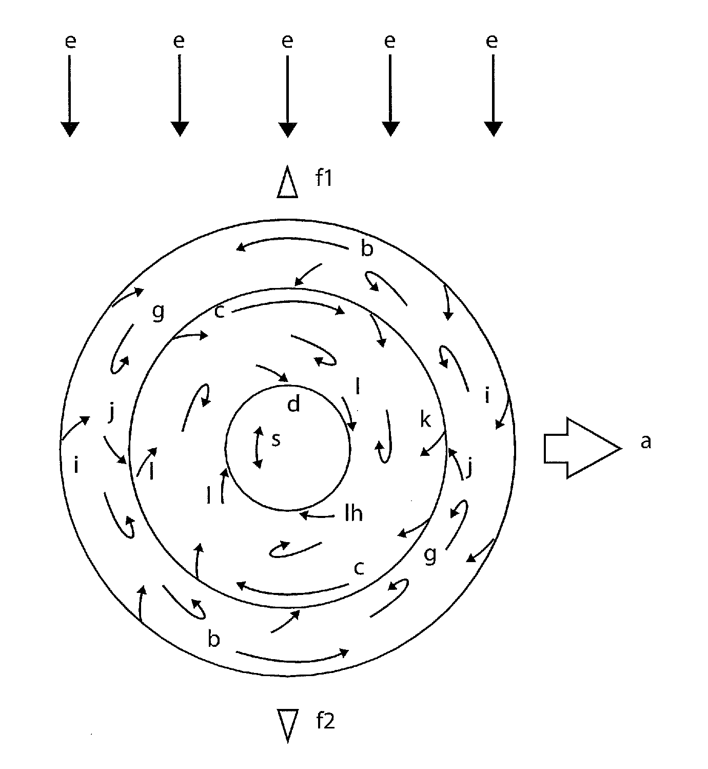
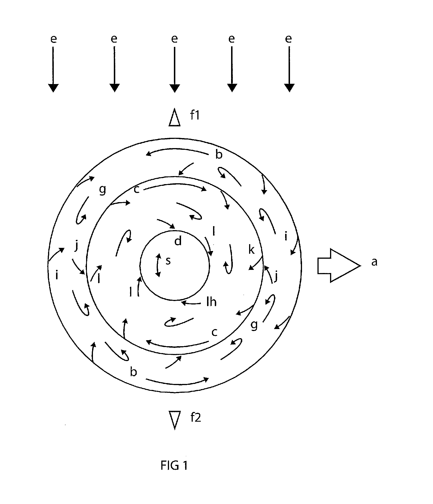
[0036]The present invention relates to an integral powered winged aircraft or “IPWA.” More specifically, the invention relates to an aircraft wherein lift is generated by two discs which rotate about a central axis. The discs generate equal and opposite forces such that the central axis remains fixed, thereby allowing it to be used for a crew or cargo compartment. In one embodiment, the two discs are concentrically located. The various components of the present invention, and the manner in which they interrelate, will be described in greater detail hereinafter.

[0037]FIG. 1 is a top view of an IPWA which shows the general location of the aerodynamic forces which act on the vehicle and must be counteracted, controlled, or converted to the vehicle advantage. In FIG. 1“a” is the direction of travel, “b” is outer disc direction of rotation, “c” is the inner disc direction of rotation, “d” is the non-rotating canopy that closes the aperture in the center of the inner disc, “e” is a crossw...


PUM


Abstract

Disclosed is a Powered Wing Aircraft. A generalized stabilizer/directional vent is used for providing a standard range of aeronautical control. It controls cross winds, directional velocity, directional control, and torque balancing in one simple easy to control device. It is attached to the axles. These improvements can apply to both military and civilian applications.

Description

CROSS REFERENCE TO RELATED APPLICATIONS[0001]This application claims priority to and is a continuation-in-part of application Ser. No. 12 / 501,971 filed on Jul. 13, 2009 and entitled “Integral Powered Wing Aircraft.” The '971 application is a divisional of and claims priority to application Ser. No. 11 / 521,597 filed on Sep. 14, 2006 and entitled “Integral Powered Wing Aircraft” (now U.S. Pat. No. 7,559,506). The '597 application, in turn, claims priority to provisional application Ser. No. 60 / 717,145 filed on Sep. 14, 2005 entitled. “Integral Powered Wine Aircraft.” The contents of all the foregoing applications are fully incorporated herein by reference for all purposes.BACKGROUND OF THE INVENTION[0002]1. Field of the Invention[0003]This application relates to an integral powered winged aircraft (or “IPWA”). More specifically, the present invention relates to an aircraft design consisting of two concentrically oriented contra-rotating discs, whereby rotational forces generated by th...

Claims


Application Information

Patent Timeline
Patent Type & Authority Applications(United States)
IPC IPC(8): B64C39/06
CPCB64C39/001B64C39/024B64C39/064F41H7/00B64C2201/108F41A23/00F41H5/24B64C2201/027B64U10/13B64U30/20B64C29/0025
Inventor KISSEL, JR., WALDEMAR F.
Owner WFK & ASSOC
Why Eureka
Try Eureka