
Zero-wall clearance linkage mechanism for providing additional layout

a technology of lateral adjustment and linkage mechanism, which is applied in the direction of chairs, mechanical control devices, instruments, etc., can solve the problems of reducing the service life of the unit, and requiring relatively complex linkage mechanisms, so as to prevent the seating unit from slipping and reducing the cost. , the effect of cost saving

Inactive Publication Date: 2012-03-01
L & P PROPERTY MANAGEMENT CO
View PDF6 Cites 69 Cited by
  • Summary
  • Abstract
  • Description
  • Claims
  • Application Information

AI Technical Summary

Benefits of technology

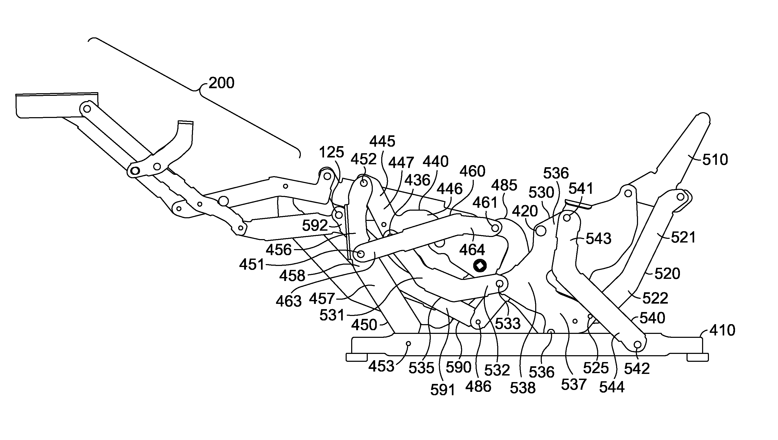
[0010]Embodiments of the present invention seek to provide a simplified linkage mechanism that can be assembled to a compact motor and that can be adapted to essentially any type of seating unit. In an exemplary embodiment, the compact motor in concert with the linkage mechanism can achieve full movement and sequenced adjustment of the seating unit between the closed, extended, and reclined positions. The compact motor may be employed in a proficient and cost-effective manner to adjust the linkage mechanism without creating interference or other disadvantages appearing in the conventional designs that are inherent with automation. The linkage mechanism may be configured with features that assist in preventing tipping of the seating unit, sequencing the seating-unit adjustment between positions, locking a footrest assembly in an extended position, and curing other disadvantages appearing in the conventional designs.

Problems solved by technology

However, these seating units require relatively complex linkage mechanisms to afford this capability.
The complex linkage assemblies limit certain design aspects when incorporating automation.
In particular, these linkage assemblies impose constraints on incorporating a single motor for automating adjustment between the positions mentioned above, and require two or more motors to accomplish automation of each adjustment.
In addition, the lack of lateral adjustment offered by the conventional complex linkage mechanisms disadvantageously requires the entire seating unit to be moved outwardly away from an adjacent wall.
Further, when employing motorized adjustment to the conventional complex linkage mechanisms, the seating unit housing these mechanisms is susceptible to tipping forward when adjusted to the reclined position.
Even further, motorized adjustment of the conventional complex linkage mechanisms often causes the ottoman(s) and the backrest of the seating unit to move out of sequence.
For example, when adjusting from the closed position to the extended position, a pressure generated by the occupant's legs on the ottoman(s) may cause resistance in extending the footrest assembly.

Method used


Image

  • Zero-wall clearance linkage mechanism for providing additional layout
  • Zero-wall clearance linkage mechanism for providing additional layout
  • Zero-wall clearance linkage mechanism for providing additional layout

Examples


Embodiment Construction

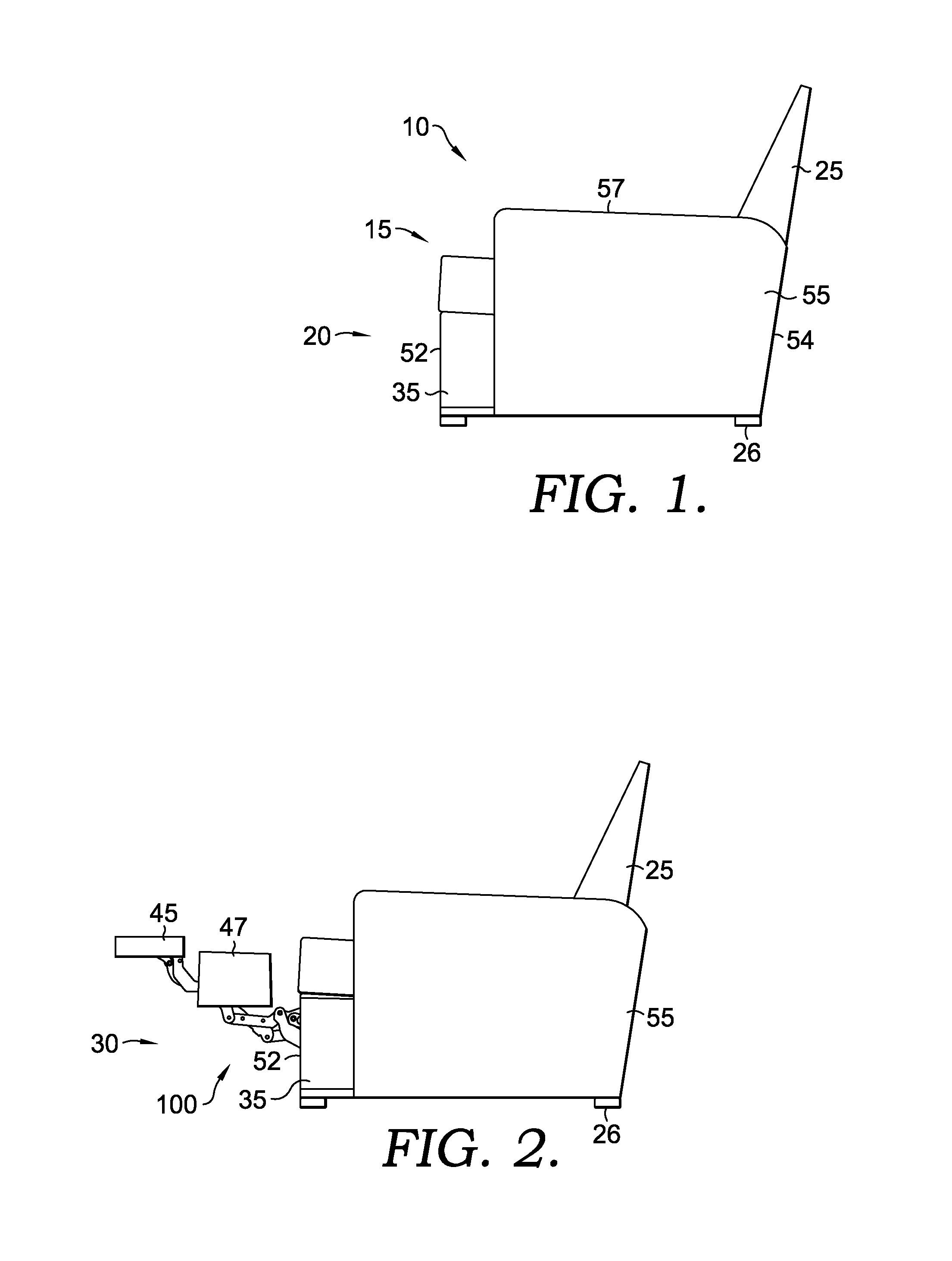
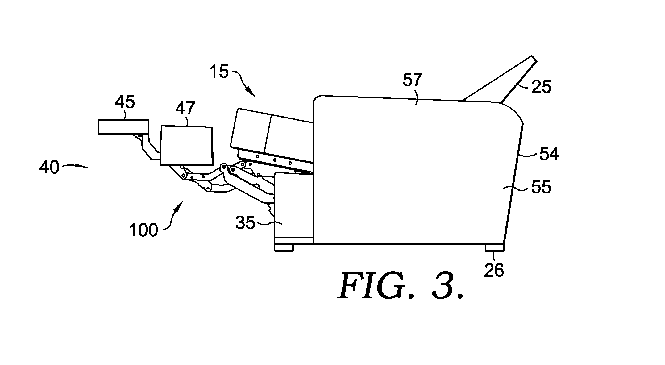
[0031]FIGS. 1-3 illustrate a seating unit 10. Seating unit 10 has a seat 15, a backrest 25, legs 26 (e.g., support bushings 411 and 412 of FIGS. 5 and 15), a linkage mechanism 100, a first foot-support ottoman 45, a second foot-support ottoman 47, a stationary base 35, and a pair of opposed arms 55. Stationary base 35 has a forward section 52, a rearward section 54, and is supported by the legs 26, where the legs 26 support the stationary base 35 and raise it above an underlying surface (not shown). In addition, the stationary base 35 is interconnected to the seat 15 via the linkage mechanism 100 that is generally disposed between the pair of opposed arms 55, and the rearward section 54. Seat 15 is moveable over the stationary base 35 during adjustment of the seating unit 10. In embodiments, the seat 15 is moveable according to the arrangement of the linkage mechanism 100 such that no portion of the seat 15 interferes with the opposed arms 55 throughout adjustment.

[0032]Opposed arms...


PUM


Abstract

A seating unit that includes a linkage mechanism adapted to adjust between closed, extended, and reclined positions is provided. The linkage mechanism includes a seat-mounting plate mounted to a footrest assembly, a back-mounting link and a rear bellcrank both rotatably coupled to the seat-mounting plate, an activator bar that controls a footrest drive link, and a linear actuator for carrying out automated adjustment of the linkage assembly. In operation, a stroke in a first phase of the linear actuator generates a torque on the activator bar. The footrest drive link converts the torque into a laterally-directed force that pushes the footrest assembly into the extended position. A stroke in the second phase acts to push the activator bar forward and translate the seat-mounting plate forward at a consistent inclination angle. The forward translation causes the rear bellcrank to rotate, thereby biasing the back-mounting link rearward into the reclined position.

Description

CROSS-REFERENCE TO RELATED APPLICATIONS[0001]None.STATEMENT REGARDING FEDERALLY SPONSORED RESEARCH OR DEVELOPMENT[0002]None.BACKGROUND OF THE INVENTION[0003]The present invention relates broadly to motion upholstery furniture designed to support a user's body in an essentially seated disposition. Motion upholstery furniture includes recliners, incliners, sofas, love seats, sectionals, theater seating, traditional chairs, and chairs with a moveable seat portion, such furniture pieces being referred to herein generally as “seating units.” More particularly, the present invention relates to an improved linkage mechanism developed to accommodate a wide variety of styling for a seating unit, which is otherwise limited by the configurations of linkage mechanisms in the field. Additionally, the improved linkage mechanism of the present invention provides for reclining a seating unit that is positioned against a wall or placed within close proximity of other fixed objects.[0004]Reclining se...

Claims


Application Information

Patent Timeline
Patent Type & Authority Applications(United States)
IPC IPC(8): A47C1/035A47C1/038A47C7/00A47C1/0355
CPCY10T74/20594A47C1/0342A47C1/0355
Inventor LAWSON, GREGORY M.LAKE, STEPHEN
Owner L & P PROPERTY MANAGEMENT CO
Learn More