Electronic device, camera, camera system, position measurement operation control program and position measurement operation control method

a technology of position measurement and operation control, which is applied in the field of electronic devices, camera systems, position measurement operation control programs and position measurement operation control methods, can solve the problems of unnecessary use of battery power in the camera, and achieve the effect of minimizing the power consumption necessitating the position measurement operation

Inactive Publication Date: 2012-03-01
NIKON CORP
View PDF6 Cites 6 Cited by
  • Summary
  • Abstract
  • Description
  • Claims
  • Application Information

AI Technical Summary

Benefits of technology

[0027]According to the present invention, the position measurement operation is disallowed in response to a detection sign...

Problems solved by technology

This gives rise to an issue in that the batter...

Method used


Image

  • Electronic device, camera, camera system, position measurement operation control program and position measurement operation control method
  • Electronic device, camera, camera system, position measurement operation control program and position measurement operation control method
  • Electronic device, camera, camera system, position measurement operation control program and position measurement operation control method

Examples


Embodiment Construction

[0035]The following is a description of the digital camera achieved in an embodiment of the present invention, given in reference to FIGS. 1 through 3.

[0036](Structure of the Digital Camera)

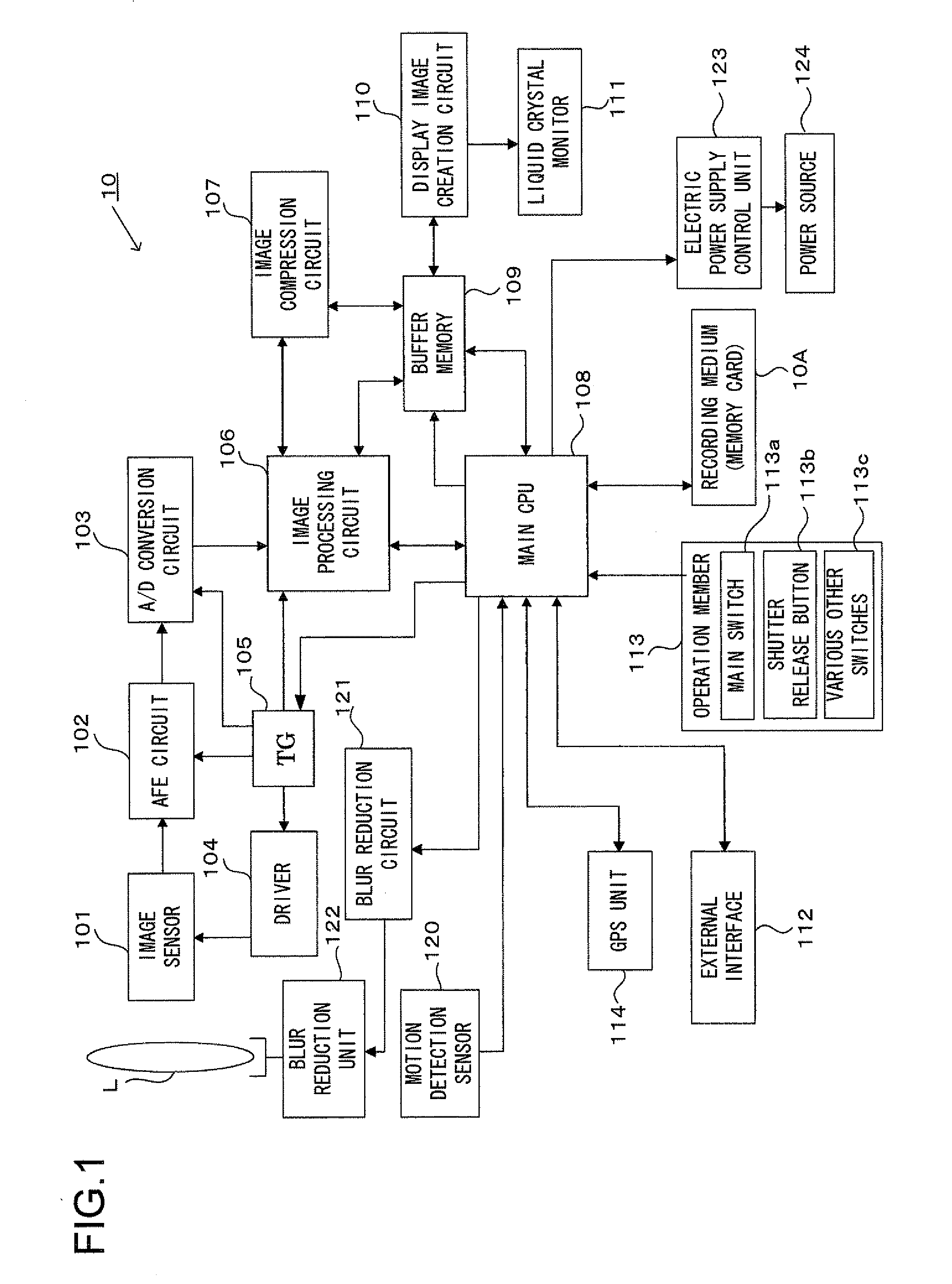
[0037]FIG. 1 is a block diagram showing the essential structure of a digital camera 10. It is to be noted that the digital camera 10 achieved in the embodiment is a camera with an integrated lens, which includes a photographic lens fixed to the camera body as an integrated part thereof. In response to an instruction output from a main CPU 108 in the digital camera structured as shown in FIG. 1, a timing generator (TG) 105 provides a timing signal to a driver 104, an AFE (analog front end) circuit 102, an A / D conversion circuit 103 and an image processing circuit 106. The driver 104 provides a drive signal required at an image sensor 101.

[0038]A subject image is formed via a photographic lens L onto an image-capturing surface of the image sensor 101. The image sensor 101 may be, for instance, a CC...


PUM


Abstract

A camera includes: a photographic lens; an image sensor that captures a subject image; a motion detection unit that detects motion of the camera and outputs a detection signal corresponding to an extent of the motion; a position measurement unit that measures a position assumed by the camera by receiving a radio wave originating from an external source; a blur reducing unit that reduces an extent of blurring in a photographic image attributable to motion of the camera in correspondence to the output value indicated in the detection signal output from the motion detection unit; and a position measurement engagement control unit that disallows engagement of the position measurement unit in operation based upon the output value indicated in the detection signal output from the motion detection unit.

Description

[0001]This application is a continuation of International Application No. PCT / JP2010 / 061043 filed Jun. 29, 2010.INCORPORATION BY REFERENCE[0002]The disclosures of the following priority applications are herein incorporated by reference:[0003]Japanese Patent Application No. 2009-155890 filed Jun. 30, 2009 PCT / JP2010 / 061043 filed Jun. 29, 2010BACKGROUND OF THE INVENTION[0004]1. Field of the Invention[0005]The present invention relates to an electronic device, a camera and a camera system each having a function of measuring the position thereof, a position measurement operation control program and a position measurement operation control method.[0006]2. Description of Related Art[0007]There are cameras known in the related art that execute position measurement by using a GPS (global positioning system) unit and recording position measurement information thus obtained as photographing location information. Japanese Laid Open Patent Publication No. 2000-56386 discloses that this type of ...

Claims


Application Information

Patent Timeline
IPC IPC(8): H04N5/228G01S19/34
CPCG03B5/00H04N5/23241H04N5/232H04N23/651H04N23/633H04N23/631
Inventor NISHIMURA, TOMOKI
Owner NIKON CORP
Why Eureka
Try Eureka