Perturbation antenna system and apparatus for wireless terminals

Inactive Publication Date: 2012-03-01
JIA DONGXUN +1
View PDF12 Cites 2 Cited by
  • Summary
  • Abstract
  • Description
  • Claims
  • Application Information

AI Technical Summary

Benefits of technology

[0015]The object of this invention is to provide a practical way to improve the existing antenna performance by adding another perturbation antenna and associated apparatus. The perturbation antenna will analogically combine with one existing primary antenna. With user's input and perception, the perturbation antenna phases can be changed to produce desired perturbation so that the overall antenna system pattern can be reshaped and redirected.
[0016]Unlike common beam formers or MRC type of diversity technologies, the invented method is simple in implementation without complicate signal processing required. The phase modification of the perturbation antenna can be achieved manually or automatically via a variable delay line circuitry which will be further detailed in the forthcoming specification.
[0018]The invented method enables terminal users to enhance their signal reception through their inputs and perception. Users can simply dial an electro-mechanical device to tune the phases for perturbation antenna and to optimize the overall antenna pattern for the best reception.

Problems solved by technology

This trend makes terminal antenna design a big challenge and a differentiator in balancing between antenna gains versus antenna form factor.
In particular, when antenna size is too small comparing to carrier frequency wavelength, the antenna will produce loss rather than gain.
It is hardly seen in user terminal side due to additions of hardware costs; more processing power required and increased software complexity.

Method used


Image

  • Perturbation antenna system and apparatus for wireless terminals
  • Perturbation antenna system and apparatus for wireless terminals
  • Perturbation antenna system and apparatus for wireless terminals

Examples


Embodiment Construction

[0026]In a real wireless environment, a large portion of signals arriving at the user terminal is in multi-path form. The angles of signal arrivals completely depend on the surrounding environments and are random in nature. In order to collect multi-path signals, conventional terminal antennas are designed isotropic. Therefore, most of the terminal antennas, if not all, has 0 dB gain or even has loss. In order to meet the SNR requirements of the 3G / 4G systems, current terminal antennas have to be improved or re-designed to gain more 2 to 3 dB SNR or even more. The object of this invention is to propose a perturbation antenna system and associated apparatus that will improve the existing user terminal antenna performance with easy implementation.

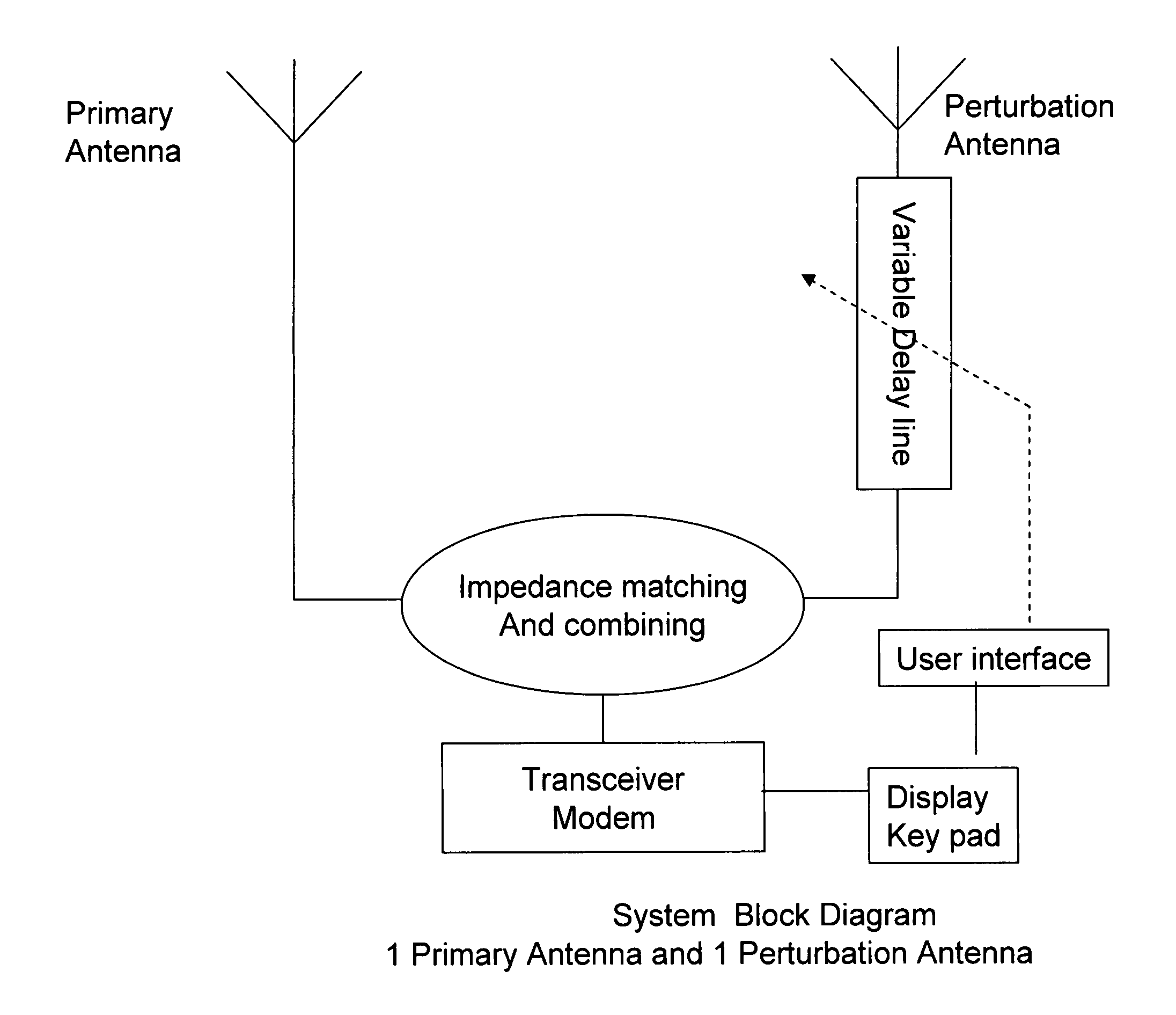
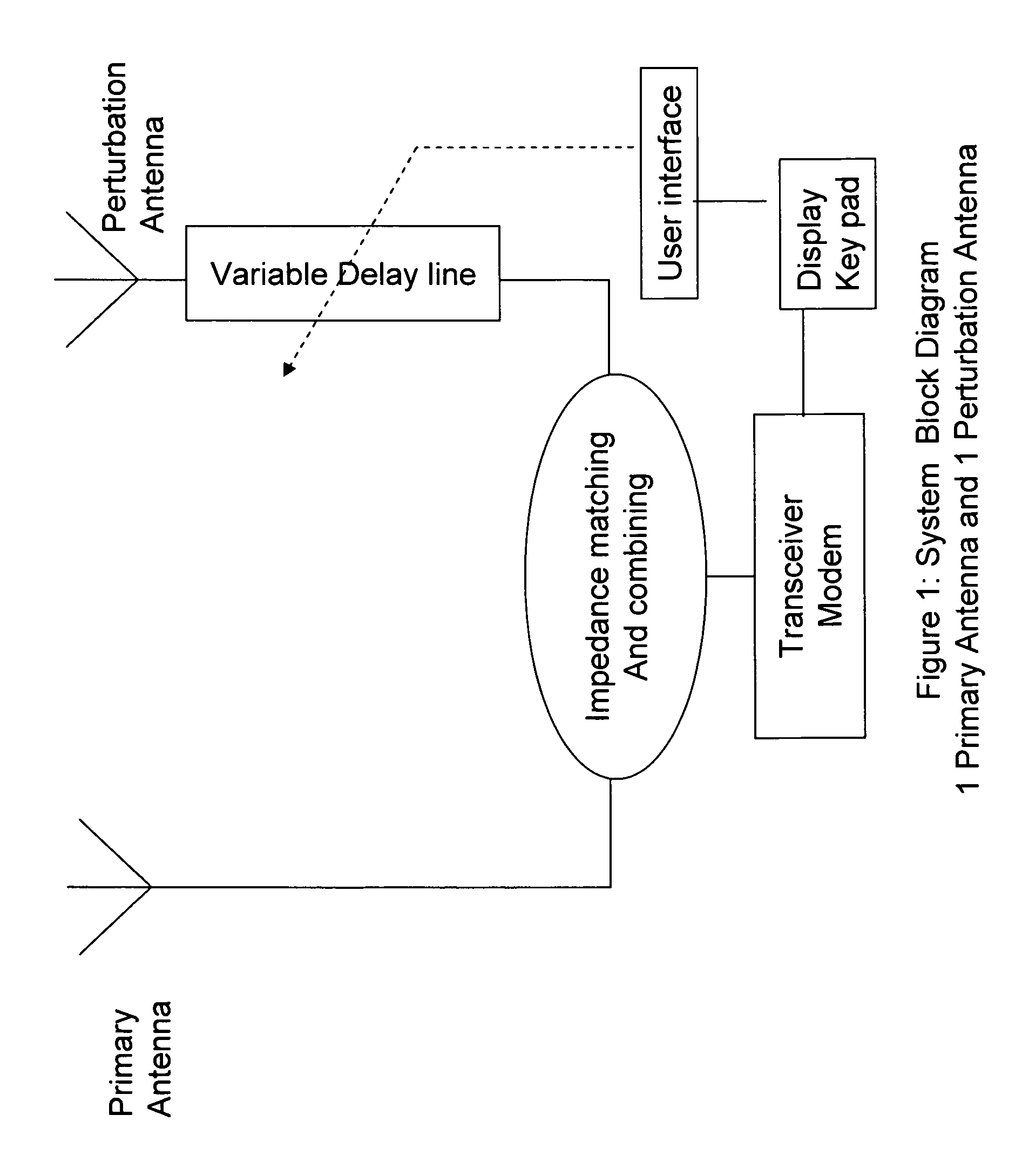
[0027]Refer to FIG. 1; there is an illustrated primary antenna along with a perturbation antenna. The primary antenna is same as the conventional ones. The perturbation antenna has a delay circuitry to alter the signal phases before the analo...


PUM


Abstract

This is invention discloses a perturbation antenna system for wireless communication terminals such mobile handsets, mobile embedded laptops, mobile CPEs (Customer premises equipment), nomadic wireless CPEs, fixed wireless terminals and etc. The perturbation antenna output is analogically combined with that of the primary antenna. The combined result is to re-create the antenna pattern shape and its direction pointing in order to achieve gains by user intercept. A variable delay circuitry is equipped to the perturbation antenna therefore the user's interception can be enforced via programmable apparatus either by manually or by digital inputs. The user can tune the delay parameters meanwhile observe the antenna pattern changes and the call quality until satisfaction.

Description

CLAIM OF PRIORITY[0001]This patent application claims the benefit of priority from U.S. Provisional Patent Application No. 61 / 344,579 filed on Aug. 25, 2010. This application incorporates by reference the entire disclosure of U.S. Provisional Patent Application No. 61 / 344,579.FIELD OF THE INVENTION[0002]The embodiments of the invention relate generally to wireless user terminal antenna system, apparatus and reception improvement technologies.BACKGROUND OF THE INVENTION[0003]In general, a wireless communication system has four major subsystems, i.e. antenna system, radio system, base band processing system and MAC processor. Antenna is responsible to pick up a signal or to radiate a signal; radio system will select and regulate the interested signal coming down from an antenna or regulate the signal from base band subsystem before it goes to the air; base band processing is the place where messages get processed such as encoding / decoding, modulation and demodulation, encryption / decry...

Claims


Application Information

Patent Timeline
IPC IPC(8): H04B1/38
CPCH04B1/126H04B7/0857H04B7/0828H04B7/0825
Inventor JIA, DONGXUNWU, SHIQUAN
Owner JIA DONGXUN
Why Eureka
Try Eureka