Unlock instant, AI-driven research and patent intelligence for your innovation.

Vehicular control device and method of controlling a vehicle

a technology of vehicle control and control device, which is applied in the direction of machine/engine, process and machine control, and propulsion using engine-driven generators. it can solve the problem of not being able to achieve satisfactorily responsive engine braking

Inactive Publication Date: 2015-07-21
TOYOTA JIDOSHA KK
View PDF27 Cites 0 Cited by
  • Summary
  • Abstract
  • Description
  • Claims
  • Application Information

AI Technical Summary

Benefits of technology

The system ensures that the vehicle manifests engine braking force with good responsiveness by rapidly adjusting the internal combustion engine's rotation speed in accordance with the driver's intended shifts, preventing delays and improving the overall braking experience.

Problems solved by technology

This cannot achieve a satisfactorily responsive engine braking effect as intended by the driver.

Method used


Image

  • Vehicular control device and method of controlling a vehicle
  • Vehicular control device and method of controlling a vehicle
  • Vehicular control device and method of controlling a vehicle

Examples


Embodiment Construction

[0032]Hereinafter reference will be made to the drawings to describe an embodiment of the present invention. In the following description, identical components are identically denoted. Their names and functions are also identical. Accordingly, they will not be described repeatedly in detail.

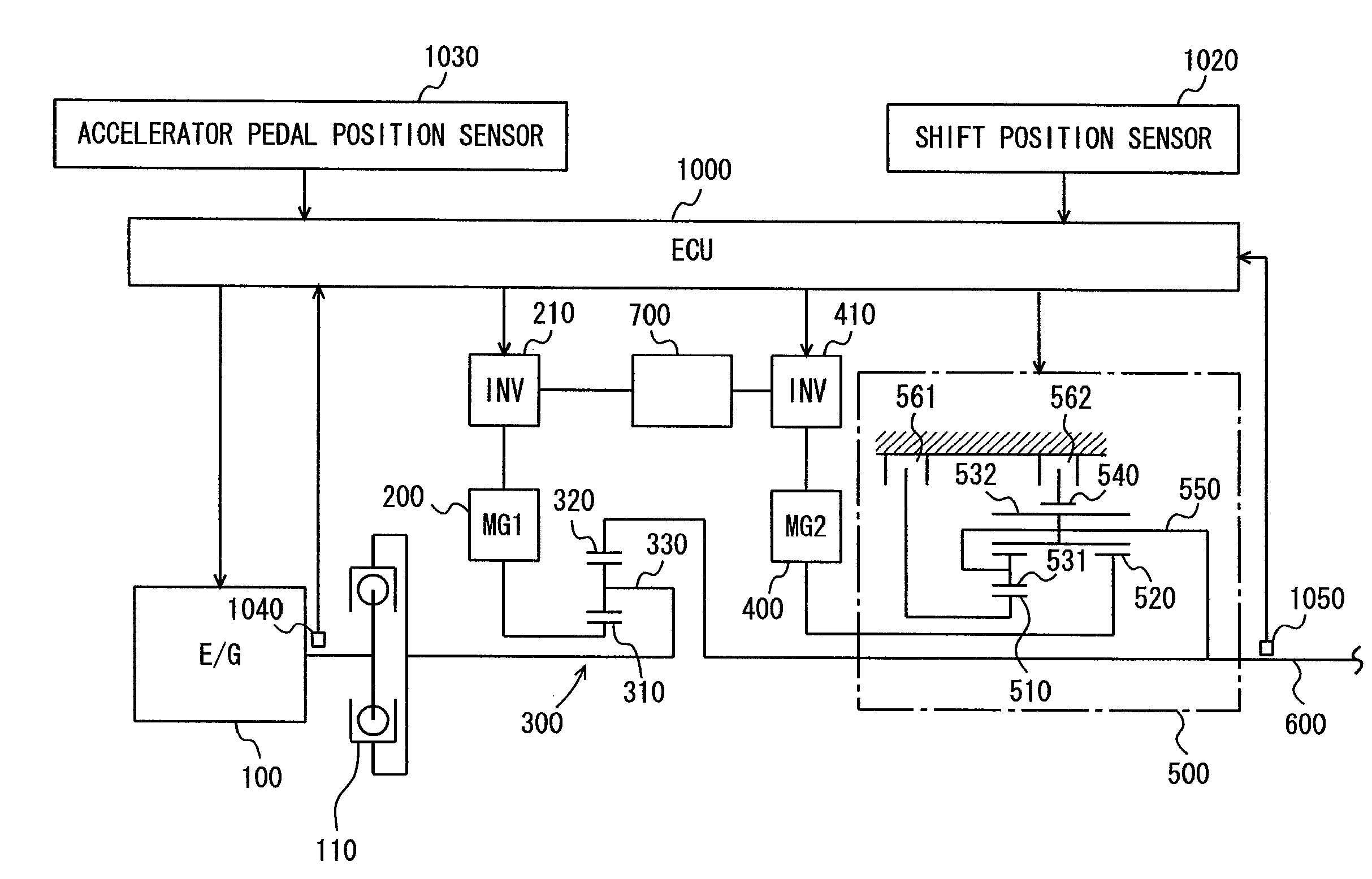
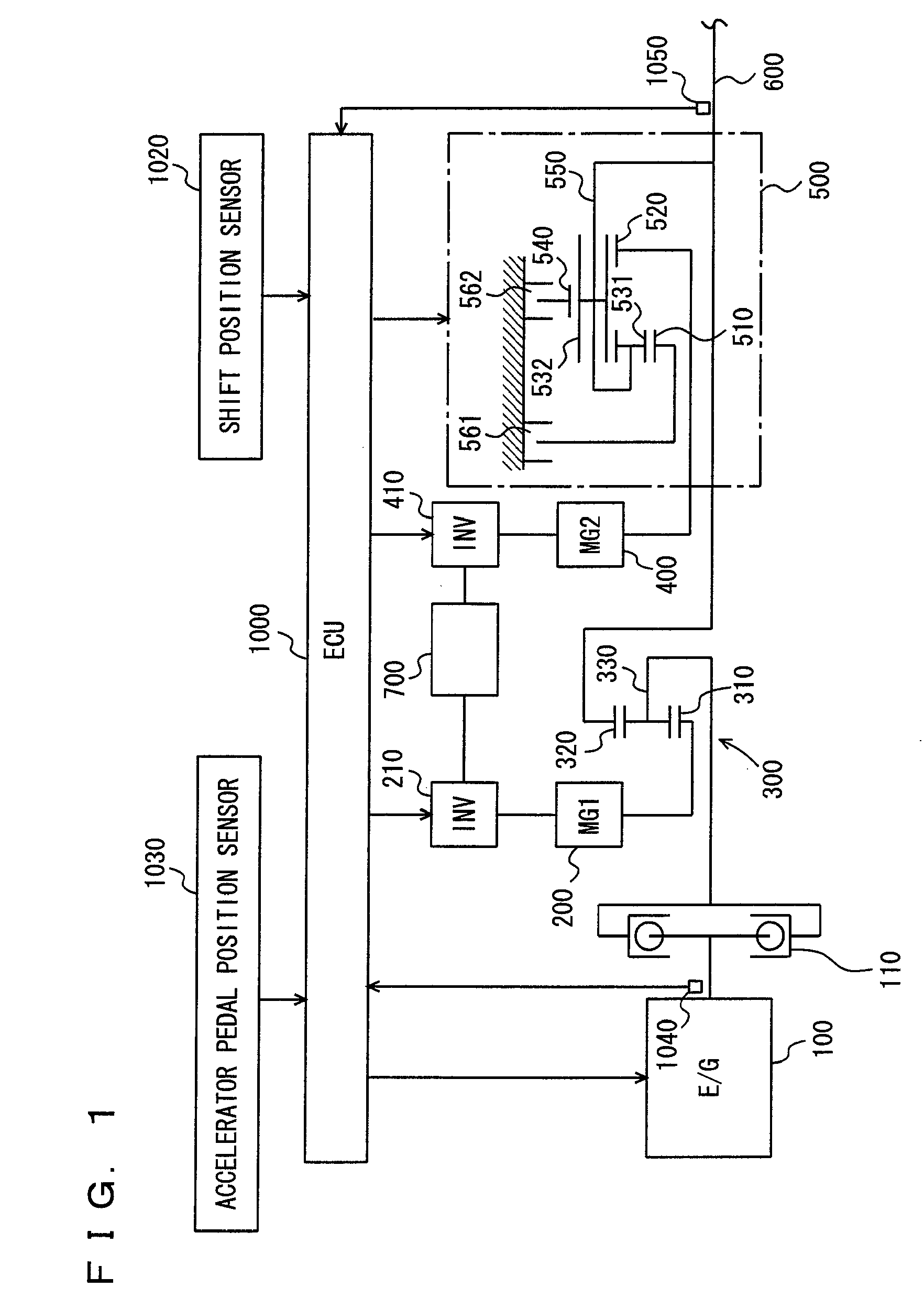
[0033]With reference to FIG. 1, the present embodiment provides a control device mounted in a hybrid vehicle having a power train as will be described hereinafter. Note that the control device of the present embodiment is implemented by a program executed by an electronic control unit (ECU) 1000.

[0034]As shown in FIG. 1, the power train is configured mainly of an engine 100, a motor generator (MG) (1) 200, a power split device 300 adding or splitting a torque between engine 100 and MG (1) 200, an MG (2) 400, and a transmission 500.

[0035]Engine 100 has an output shaft coupled via power split device 300 to MG (1) 200 generating electric power based on motive power of engine 100. Power split device ...


PUM


Abstract

An ECU executes a program including the steps of: calculating a period of time elapsing after a stage was immediately previously shifted before the stage is currently shifted; if the elapsed period of time is at most a predetermined period of time, performing a process to advance an elevation rate applied to the rotation speed of an engine; determining an elevation rate applied to the rotation speed of the engine; and performing a process to control elevating the rotation speed of the engine.

Description

[0001]This is a 371 national phase application of PCT / JP2007 / 064629 filed 19 Jul. 2007, claiming priority to Japanese Patent Application No. 2006-341664 filed 19 Dec. 2006, the contents of which are incorporated herein by reference.TECHNICAL FIELD[0002]The present invention relates to controlling a vehicle that has an internal combustion engine and a rotating electric machine as driving sources in response to an operation of the driver to vary engine braking force stepwise, and particularly to controlling the vehicle in response to the driver's operation to set a rate of change that is applied to the rotation speed of the internal combustion engine.BACKGROUND ART[0003]Conventionally there have been a large number of techniques implementing force driving vehicles to meet drivers' demands. For example, Japanese Patent Laying-open No. 2006-020481 discloses a motive power output device achieving a good feel for driving. This motive power output device is capable of outputting motive pow...

Claims


Application Information

Patent Timeline
Patent Type & Authority Patents(United States)
IPC IPC(8): B60K6/445B60W30/18B60W10/06B60L11/14B60L7/14B60K6/547F02D41/02B60W10/08B60L11/12B60K6/365B60W10/115F16H37/08F16H3/72F02D31/00B60W20/00B60K1/02B60L50/15B60L50/16
CPCB60K6/445B60K6/365B60K6/547B60L7/14B60L11/123B60L11/14B60W10/06B60W10/08B60W10/115B60W30/18127F02D41/023B60K1/02B60L2240/441B60L2240/486B60L2240/80B60W20/00B60W2510/0638B60W2510/1005B60W2520/10B60W2540/10B60W2710/0644B60W2710/0661F02D31/001F16H3/728F16H2037/0873Y02T10/6217Y02T10/6239Y02T10/6286Y02T10/7077B60L50/61B60L50/16Y02T10/62Y02T10/7072Y02T10/70B60W10/10B60W2510/0652
Inventor AOKI, TAKANORI
Owner TOYOTA JIDOSHA KK