
Transmission Assemblies

Active Publication Date: 2012-03-01
IROBOT CORP
View PDF8 Cites 20 Cited by
  • Summary
  • Abstract
  • Description
  • Claims
  • Application Information

AI Technical Summary

Benefits of technology

[0008]The present teachings provide a transmission assembly for a remote vehicle. The transmission assembly comprises a motor and is able to shift between a first higher-torque lower-speed output operational state and a second lower-torque higher-speed output operational state at any time independent of a load on or a speed of the motor. The transmission assembly is configured to be stable within the first and second operational states, requiring no energy to maintain the first or second operat

Problems solved by technology

Due to size and weight constraints, transmissions are typically not used in small electric systems (i.e., with small electric motors), such as, for example, robotic joints and small mobile robots.
Because small motors are generally not capa

Method used


Image

  • Transmission Assemblies
  • Transmission Assemblies
  • Transmission Assemblies

Examples


Example

[0022]Reference will now be made in detail to exemplary embodiments of the present teachings, examples of which are illustrated in the accompanying drawings.

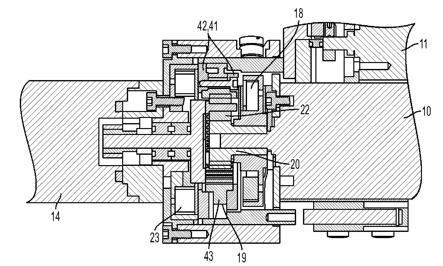
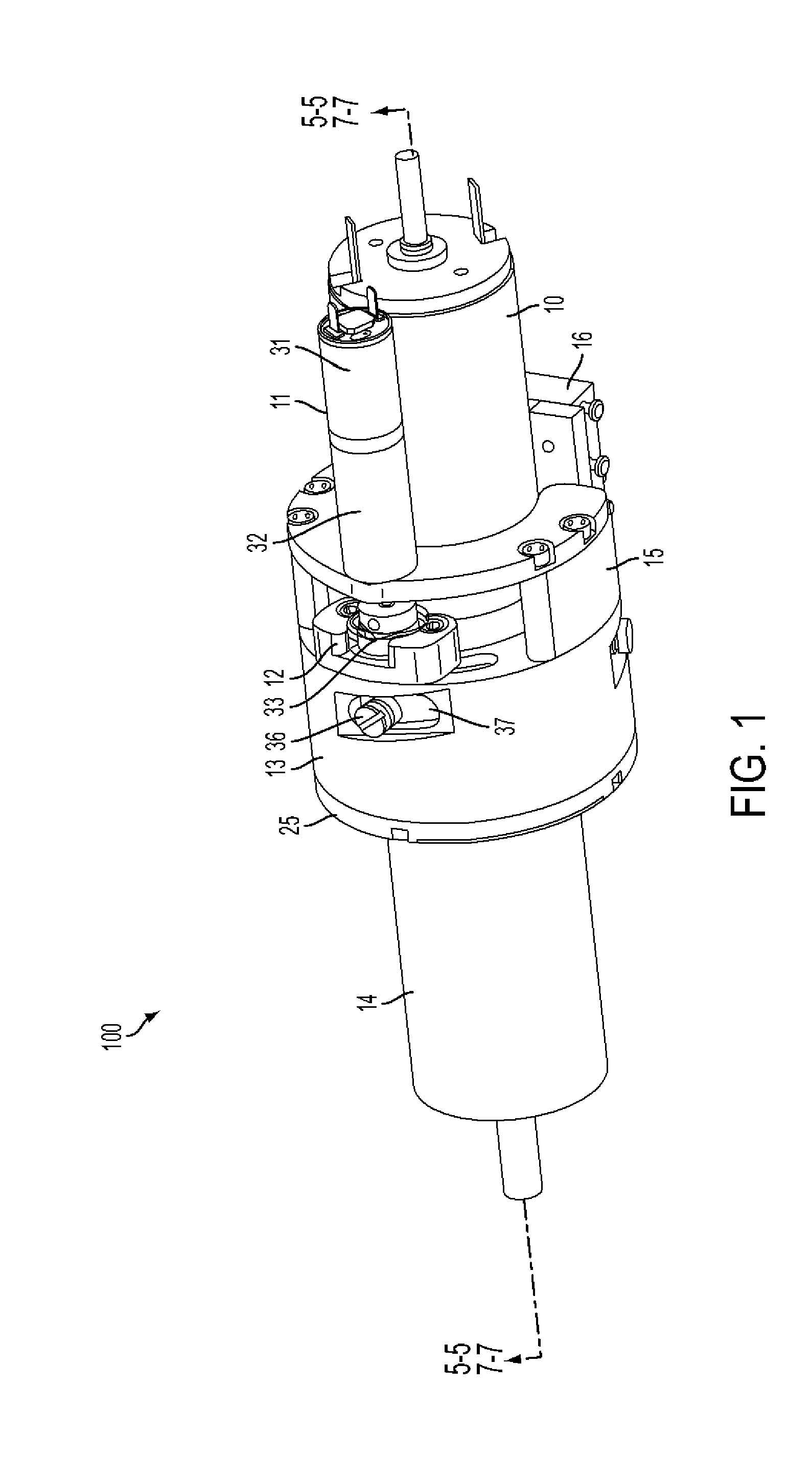
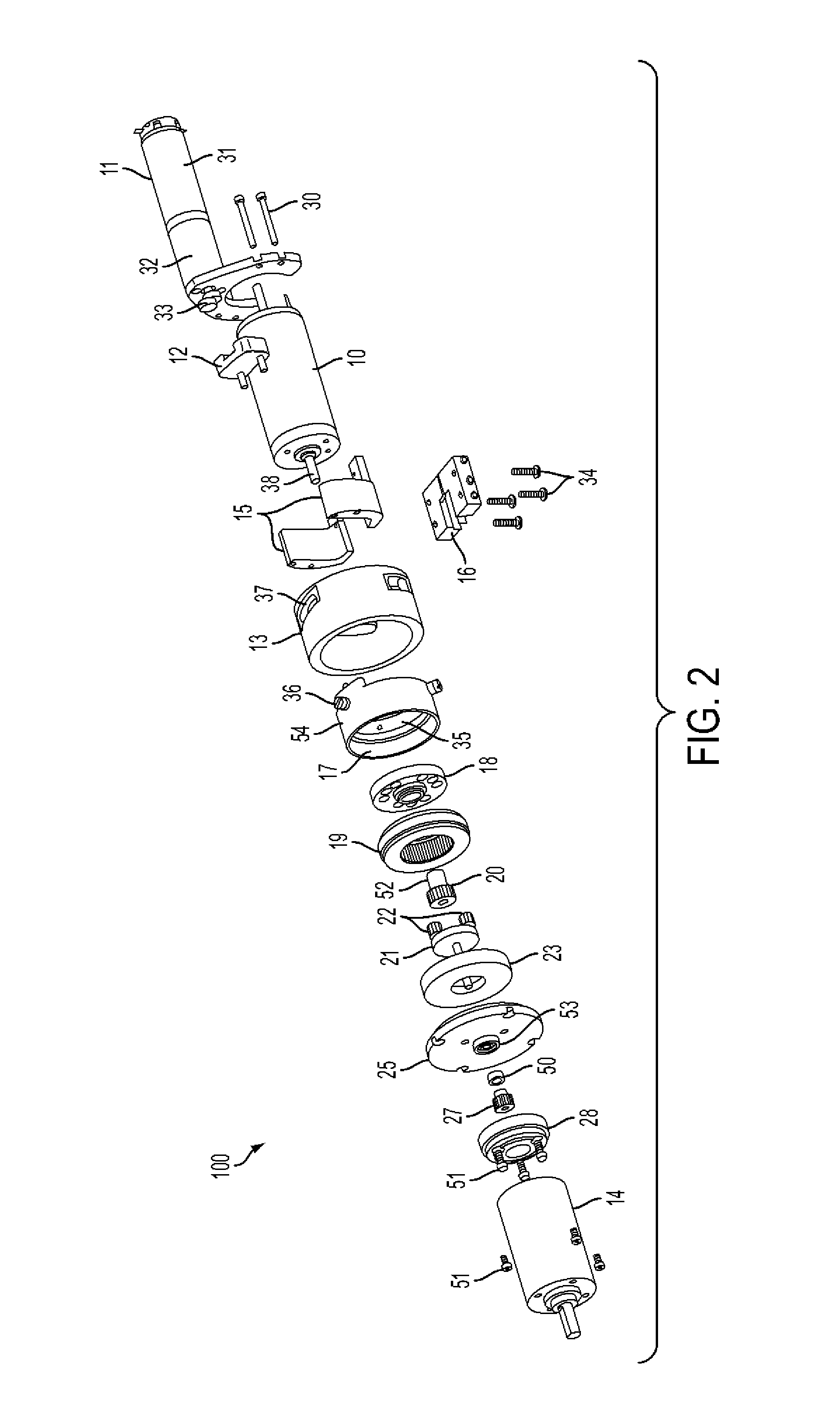
[0023]The present teachings relate to automatic, multi-speed transmission assemblies for small motors, such as, for example, motors on and / or integrated with a manipulator arm on a remote vehicle such as an iRobot® PackBot®. Two operational states, a weak / fast state comprising a low torque output and a high speed, and a strong / slow state comprising a high torque output and a low speed, can be achieved in accordance with the present teachings by utilizing a planetary gear-based, two-speed shifter comprising a sun gear, a ring gear, and a planet carrier comprising at least one planet gear. An actuator mechanism may be used to shift the ring gear between a first mode (e.g., a direct-drive mode) and a second mode (e.g., a low-gear mode). In the direct-drive mode, the ring gear is locked to and rotates with the sun gear. Thus, the pl...


PUM


Abstract

A transmission assembly comprises: a motor; a shift actuator mechanism coupled to the motor; a sun gear coupled to an output shaft of the motor; a first magnet assembly coupled to the sun gear; a ring gear assembly coupled to a shift coupler, the shift coupler being configured to engage via the shift actuator mechanism; a second magnet assembly coupled to a housing face plate, the housing face plate being coupled to an output gear box; and a planet carrier coupled to an output pinion in communication with the output gearbox. The planet carrier comprises at least one planet gear. In a first mode, the ring gear is locked to the first magnet assembly and configured to rotate with the sun gear, the ring gear being configured to prevent the rotation of the at least one planet gear about its own axis causing the planet carrier to rotate at the same speed as the sun gear. In a second mode, the ring gear is locked to the second magnet assembly allowing the sun gear to engage the at least one planet gear, the sun gear being configured to rotate the at least one planet gear about its own axis causing the planet carrier to rotate at a reduced speed from the sun gear.

Description

INTRODUCTION[0001]This application claims priority to U.S. Provisional Patent Application Ser. No. 61 / 353,397, filed Jun. 10, 2010, titled Transmission Assemblies, the entire content of which is incorporated by reference herein.[0002]The present teachings relate generally to transmission assemblies. More specifically, the present teachings relate to automatic, two-speed transmission assemblies for small motors, such as, for example, electric, gas, or hydraulic motors integrated with robotic joints.BACKGROUND[0003]The section headings used herein are for organizational purposes only and are not to be construed as limiting the subject matter described in any way.[0004]A transmission or gearbox generally provides speed and torque conversions from a rotating power source, such as, for example, a motor, to another device using gear ratios. In large electric systems, such as, for example, electric vehicle drive trains, a transmission adapts the output of an electric motor to a vehicle's d...

Claims


Application Information

Patent Timeline
IPC IPC(8): F16H1/28
CPCF16H3/54B25J9/102F16H57/08F16H2200/0034F16H2200/2005F16H2200/2035
Inventor OHM, TIMOTHY R.CLAFFEE, MARK ROBERTBUEHLER, MARTINBRANCAZIO, DAVID
Owner IROBOT CORP
Learn More