Telephoto lens system

a telephoto lens and focusing type technology, applied in the field of telephoto lens systems, can solve the problems of insufficient brightness and weight reduction of telephoto lenses at the same time, and none of them can provide both sufficient brightness and sufficient weight reduction, so as to achieve the effect of reducing weigh

Active Publication Date: 2012-03-08
SAMSUNG ELECTRONICS CO LTD
View PDF4 Cites 18 Cited by
  • Summary
  • Abstract
  • Description
  • Claims
  • Application Information

AI Technical Summary

Benefits of technology

[0009]An embodiment of the invention provides a bright telephoto lens system including a focusing lens group with a reduced weight.

Problems solved by technology

However, such bright lenses are relatively large and heavy, and thus auto-focusing cameras experience slow focusing with such lenses.
Although various focusing mechanisms have been suggested to resolve the slow focusing, none of them may provide both sufficient brightness and sufficient weight reduction at the same time.
However, due to such a large number of lenses, the telephoto lens provides insufficient weight reduction.
On the other hand, a telephoto lens with a relatively reduced weight includes a small number of lenses, for example, one or two lenses, exhibits a relatively high F number, e.g., about 2, and thus the telephoto lens provides insufficient brightness.
Furthermore, due to recently increasing demands for image quality, effects of hand shakes are not negligible, and thus demands for hand shake correction are increasing.
However, lenses in F1.4 class do not have a hand shake correction feature.

Method used


Image

  • Telephoto lens system
  • Telephoto lens system
  • Telephoto lens system

Examples


first embodiment

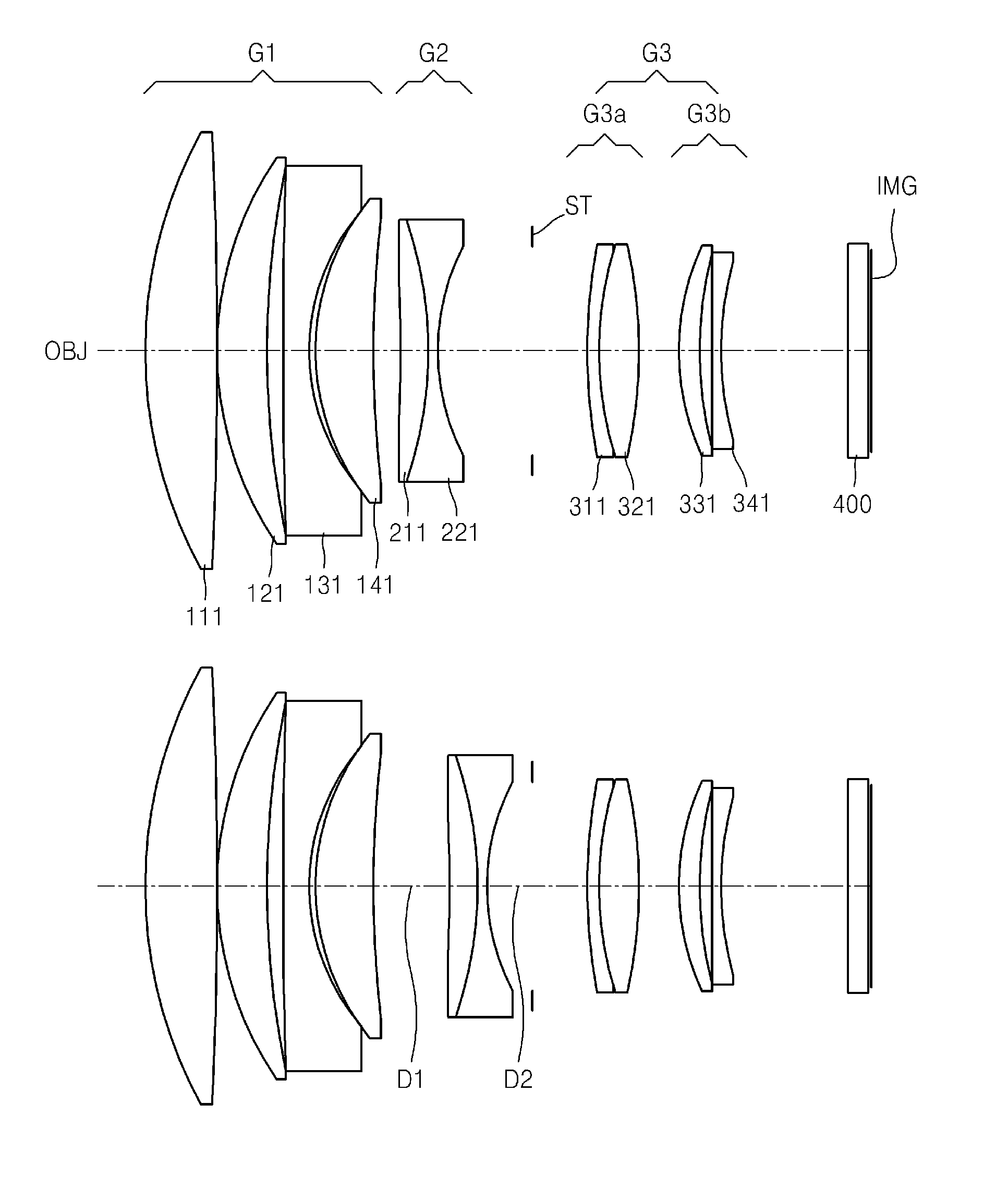
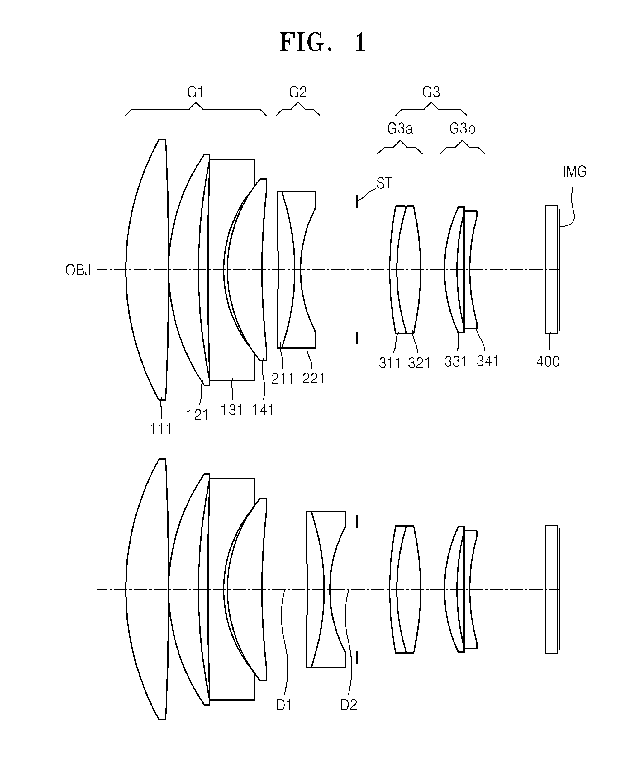
[0090]FIG. 1 shows optical arrangements of a telephoto lens system according to a first embodiment of the invention at an infinite object position and at a closest object position. The telephoto lens system includes a first lens group G1 having a positive refractive power, a second lens group G2 having a negative refractive power, and a third lens group G3 having a positive refractive power. The first lens group G1 includes a first lens 111 as a positive lens, a second lens 121 as a positive lens, a third lens 131 as a negative lens, and a fourth lens 141 as a positive lens. The second lens group G2 includes a fifth lens 211 as a positive lens, and a sixth lens 221 as a negative lens. The fifth lens 211 and the sixth lens 221 are adhered to each other and form a doublet lens. The third lens group G3 includes the 3a sub-lens group G3-a and the 3b sub-lens group G3-b. The 3a sub-lens group G3-a includes a seventh lens 311 as a negative lens, and an eighth lens 321 as a positive lens, ...

second embodiment

[0094]FIG. 9 shows optical arrangements of a telephoto lens system according to a second embodiment of the invention. The telephoto lens system includes the first lens group G1 having a positive refractive power, the second lens group G2 having a negative refractive power, and a third lens group G3 having a positive refractive power. The first lens group G1 includes a first lens 112 as a positive lens, a second lens 122 as a positive lens, a third lens 132 as a negative lens, and a fourth lens 142 as a positive lens. The second lens group G2 includes a fifth lens 212 as a positive lens, and a sixth lens 222 as a negative lens. The fifth lens 212 and the sixth lens 222 are adhered to each other and form a doublet lens. The third lens group G3 includes the 3a sub-lens group G3-a and the 3b sub-lens group G3-b. The 3a sub-lens group G3-a includes a seventh lens 312 as a negative lens, an eighth lens 322 as a positive lens, and a ninth lens 332 as a negative lens, wherein the seventh le...

third embodiment

[0097]FIG. 16 shows optical arrangements of a telephoto lens system according to a third embodiment of the invention. The telephoto lens system includes the first lens group G1 having a positive refractive power, the second lens group G2 having a negative refractive power, and a third lens group G3 having a positive refractive power. The first lens group G1 includes a first lens 113 as a positive lens, a second lens 123 as a positive lens, a third lens 133 as a negative lens, and a fourth lens 143 as a positive lens. The second lens group G2 includes a fifth lens 223 as a negative lens. The third lens group G3 includes the 3a sub-lens group G3-a and the 3b sub-lens group G3-b. The 3a sub-lens group G3-a includes a sixth lens 313 as a negative lens, and a seventh lens 323 as a positive lens. The 3b sub-lens group G3-b includes an eighth lens 333 as a positive lens, and a ninth lens 343 as a negative lens. Lens data is as shown below.

EFL 85.01FNO 1.44SurfRDNdVd 162.34910.7241.6180063....


PUM


Abstract

A telephoto lens system including a first lens group having a positive refractive power and including at least three positive lenses and one negative lens; a second lens group having a negative refractive power and for performing focusing by moving along an optical axis; and a third lens group having a positive refractive power and including a 3a sub-lens group with positive refractive power and a 3b sub-lens group), wherein the 3a sub-lens group includes a negative lens and a positive lens sequentially arranged from an object side d, the 3b sub-lens group includes a positive lens and a negative lens sequentially arranged from the object side, and the telephoto lens system satisfies a condition, 0.17<fb/f<0.35, where, fb indicates a back focal length in air without a filter, that is, a distance from a lens surface of the telephoto lens system closest to the image side to an imaging surface with respect to the telephoto lens system having an optical arrangement at an infinite object position in air without the filter, and f indicates an overall focal length of the telephoto lens system.

Description

CROSS-REFERENCE TO RELATED PATENT APPLICATION[0001]This application claims the benefit of Korean Patent Application No. 10-2010-0088052, filed on Sep. 8, 2010, in the Korean Intellectual Property Office, the disclosure of which is incorporated herein in its entirety by reference.BACKGROUND[0002]1. Field of the Invention[0003]The invention relates to an inner-focusing type telephoto lens system used in a digital still camera or a digital video camera.[0004]2. Description of the Related Art[0005]Recently, digital cameras or video cameras having a solid-state imaging device, such as charge-coupled devices (CCDs) and complementary metal-oxide semiconductors (CMOS), are becoming very popular.[0006]In a video camera or a digital camera, bright telephoto lenses with small F numbers are preferred. However, such bright lenses are relatively large and heavy, and thus auto-focusing cameras experience slow focusing with such lenses.[0007]Although various focusing mechanisms have been suggested ...

Claims


Application Information

Patent Timeline
Patent Type & Authority Applications(United States)
IPC IPC(8): G02B13/02
CPCG02B13/02G03B17/14G03B17/02G02B9/26G02B15/14G02B27/646G02B9/14G02B13/009G02B15/10H04N23/687
Inventor YONEYAMA, SHUJI
Owner SAMSUNG ELECTRONICS CO LTD
Why Eureka
Try Eureka