
Tankless liquid heater using a thermostatic mixing valve

a technology of mixing valve and tankless liquid heater, which is applied in the direction of lighting and heating apparatus, process and machine control, instruments, etc., can solve the problem of inherently energy inefficien

Inactive Publication Date: 2012-03-08
EEMAX
View PDF2 Cites 35 Cited by
  • Summary
  • Abstract
  • Description
  • Claims
  • Application Information

AI Technical Summary

Benefits of technology

[0003]In various aspects, the present disclosure describes embodiments of a tankless liquid heating system incorporating a mixing valve. Some embodiments of such a heating system may be installed for providing heated or tempered water for various uses, such as emergency rinsing at safety showers, hand-washing at wash stations, providing drinking water from dispensers, and so on. The heating system includes a controller that energizes a heating element based on the flow of liquid through the heating element, and the temperature of the heated liquid leaving the heating element. A thermostatic mixing valve is incorporated into the heating system, which can provide tempered liquid by mixing heated liquid with cold liquid diverted from a liquid inlet of the heating system. The thermostatic mixing valve may be configured to mix liquid responsive to a temperature set point applied on one or more of a temperature sensor and a controller of the heating system. In some embodiments, the heating system is configured to provide heated or tempered liquid free from temperature spikes that may cause injury or discomfort to a user.
[0004]In one aspect, the present invention is related to a tankless liquid heater receiving liquid at an inlet and providing heated liquid at an outlet. The tankless liquid heater may include a heating element for heating liquid received from the inlet of the liquid heater. The tankless liquid heater may include a flow sensor indicating the flow rate of the liquid received by the heating element. The tankless liquid heater may include a temperature sensor measuring the temperature of liquid exiting the heating element. The tankless liquid heater may include a controller regulating the amount of electrical current energizing the heating element responsive to the flow sensor and the temperature sensor. The controller may energize the heating element when the flow rate of the liquid exceeds a predefined value and may prevent energizing the heating element when the heated liquid exceeds a predefined temperature T1. The tankless liquid heater may include a thermostatic mixing valve for mixing the heated liquid with liquid diverted from the inlet responsive to the temperature of the heated liquid.
[0006]In some embodiments, the thermostatic mixing valve outputs liquid with a preconfigurable temperature upper limit. The thermostatic mixing valve may output heated liquid at a flow rate of at least about 0.3 gallons per minute. The thermostatic mixing valve may output heated liquid at a flow rate of about 0.3 gallons per minute to about 5.0 gallons per minute. In certain embodiments, the thermostatic mixing valve mixes the heated water with liquid diverted from the inlet when the flow rate of the liquid received by the heating element falls substantially over a short period of time. In some embodiments, the thermostatic mixing valve mixes the heated water with liquid diverted from the inlet when the flow rate of the liquid received by the heating element falls substantially instantaneously. The thermostatic mixing valve may support a liquid flow rate equal or higher than that supported by the heating element. The thermostatic mixing valve may divert a substantial amount of liquid from the inlet within a short amount of time for mixing with the heated liquid responsive to the temperature of the heated liquid.

Problems solved by technology

Although such heated tank systems can provide hot water at a relatively high flow rate, they are inherently energy inefficient because the water in the tank is continually reheated even when water is not being used on a regular basis.

Method used


Image

  • Tankless liquid heater using a thermostatic mixing valve
  • Tankless liquid heater using a thermostatic mixing valve
  • Tankless liquid heater using a thermostatic mixing valve

Examples


Embodiment Construction

[0015]This disclosure provides, in various aspects, systems for heating a liquid, for example, water. The systems may be configured to deliver, in various embodiments, hot liquids, and in particular hot water of a particular temperature and / or temperature range, at a certain flow rate and / or under various demand characteristics. Accordingly, in various embodiments, the disclosure describes systems for provision of hot water to one or more water fixtures, and in particular, for example, to a one or more fixtures with frequent and rapid changes in hot water demand. Examples of such fixtures and situations include, but are not limited to, multi-station wash basins in high traffic facilities (e.g., industrial washrooms at the end-of-shifts, washrooms in sports stadiums, etc.) and showers facilities (e.g., locker room facilities, dorm facilities, mass decontamination situations, etc.).

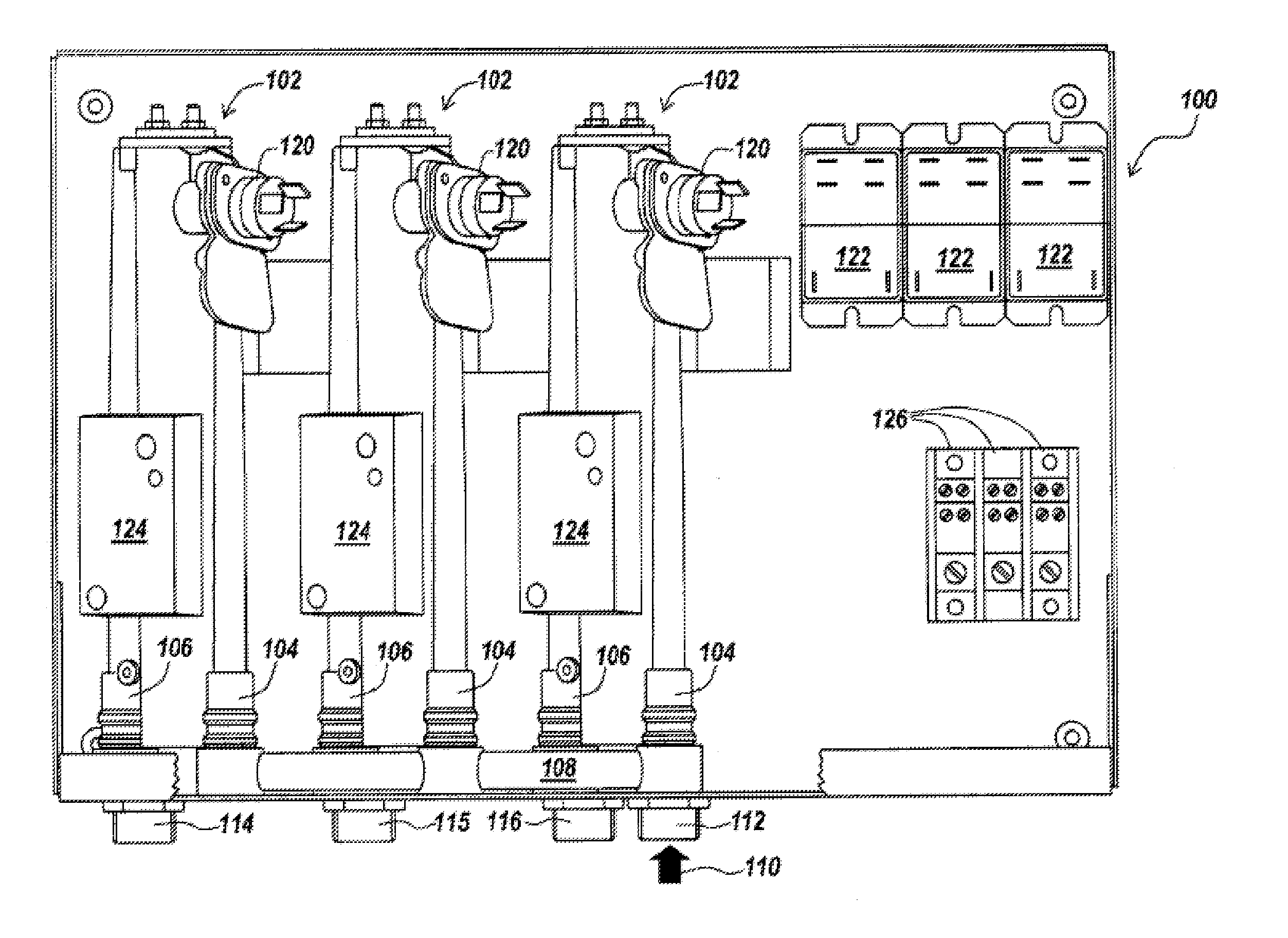
[0016]Referring to FIG. 1, in various embodiments, a tankless water heater system 100 comprises one or m...


PUM


Abstract

In various aspects, the present application describes a tankless liquid heater receiving liquid at an inlet and providing heated liquid at an outlet. The tankless liquid heater may include a heating element for heating liquid received from the inlet. A flow sensor indicates the flow rate of the liquid received by the heating element. The heater includes a temperature sensor measuring the temperature of liquid exiting the heating element. A controller of the heater regulates the amount of electrical current energizing the heating element responsive to the flow sensor and the temperature sensor, energizes the heating element when the flow rate of the liquid exceeds a predefined value and prevents energizing the heating element when the heated liquid exceeds a predefined temperature. The heater may also include a thermostatic mixing valve for mixing the heated liquid with liquid diverted from the inlet responsive to the temperature of the heated liquid.

Description

FIELD OF THE DISCLOSURE[0001]This disclosure generally relates to systems and methods for heating liquids. In particular, this disclosure relates to tankless liquid heating systems using a thermostatic mixing valve.BACKGROUND[0002]A common approach for providing hot water in both domestic and commercial settings involves the use of large tanks for the storage of hot water. Although such heated tank systems can provide hot water at a relatively high flow rate, they are inherently energy inefficient because the water in the tank is continually reheated even when water is not being used on a regular basis. Another approach to providing hot water involves the use of a tankless water heater system that heats water only when hot water is being used. Such tankless water heater systems, also referred to as demand water heater systems, can often provide a more energy efficient means of heating water than storage systems using the same type of heating (e.g., gas, electric, etc.).SUMMARY OF TH...

Claims


Application Information

Patent Timeline
IPC IPC(8): F24H1/10H05B1/02G05D23/185
CPCF24H1/142H05B1/0244F24H9/2028F24H15/184F24H15/315F24H15/238F24H15/407F24H15/37F24H15/219F24H15/128
Inventor KENNEY, JOSEPH KEVINHANKINS, JEFF
Owner EEMAX
Learn More