
Systems, methods and apparatus for propulsion

a technology of propulsion system and thrust chamber, applied in the field of rocket engines, can solve the problems of long lead time, large cooling system of thrust chamber,

Inactive Publication Date: 2012-03-15
GROTE JAMES ROBERT +1
View PDF6 Cites 24 Cited by
  • Summary
  • Abstract
  • Description
  • Claims
  • Application Information

AI Technical Summary

Problems solved by technology

The cooling system of the thrust chamber is very often a large part of a rocket engine's procurement expense and requires long lead time to manufacture.

Method used


Image

  • Systems, methods and apparatus for propulsion
  • Systems, methods and apparatus for propulsion
  • Systems, methods and apparatus for propulsion

Examples


Embodiment Construction

[0023]In the following detailed description, reference is made to the accompanying drawings that form a part hereof, and in which is shown by way of illustration specific implementations which may be practiced. These implementations are described in sufficient detail to enable those skilled in the art to practice the implementations, and it is to be understood that other implementations may be utilized and that logical, mechanical, electrical and other changes may be made without departing from the scope of the implementations. The following detailed description is, therefore, not to be taken in a limiting sense.

[0024]The detailed description is divided into six sections. In the first section, a system level overview is described. In the second section, apparatus of implementations are described. In the third section, implementations of methods are described. In the fourth section, hardware and the operating environments in conjunction with which implementations may be practiced are...


PUM

PropertyMeasurementUnit
thicknessaaaaaaaaaa
thicknessaaaaaaaaaa
thicknessaaaaaaaaaa

Abstract

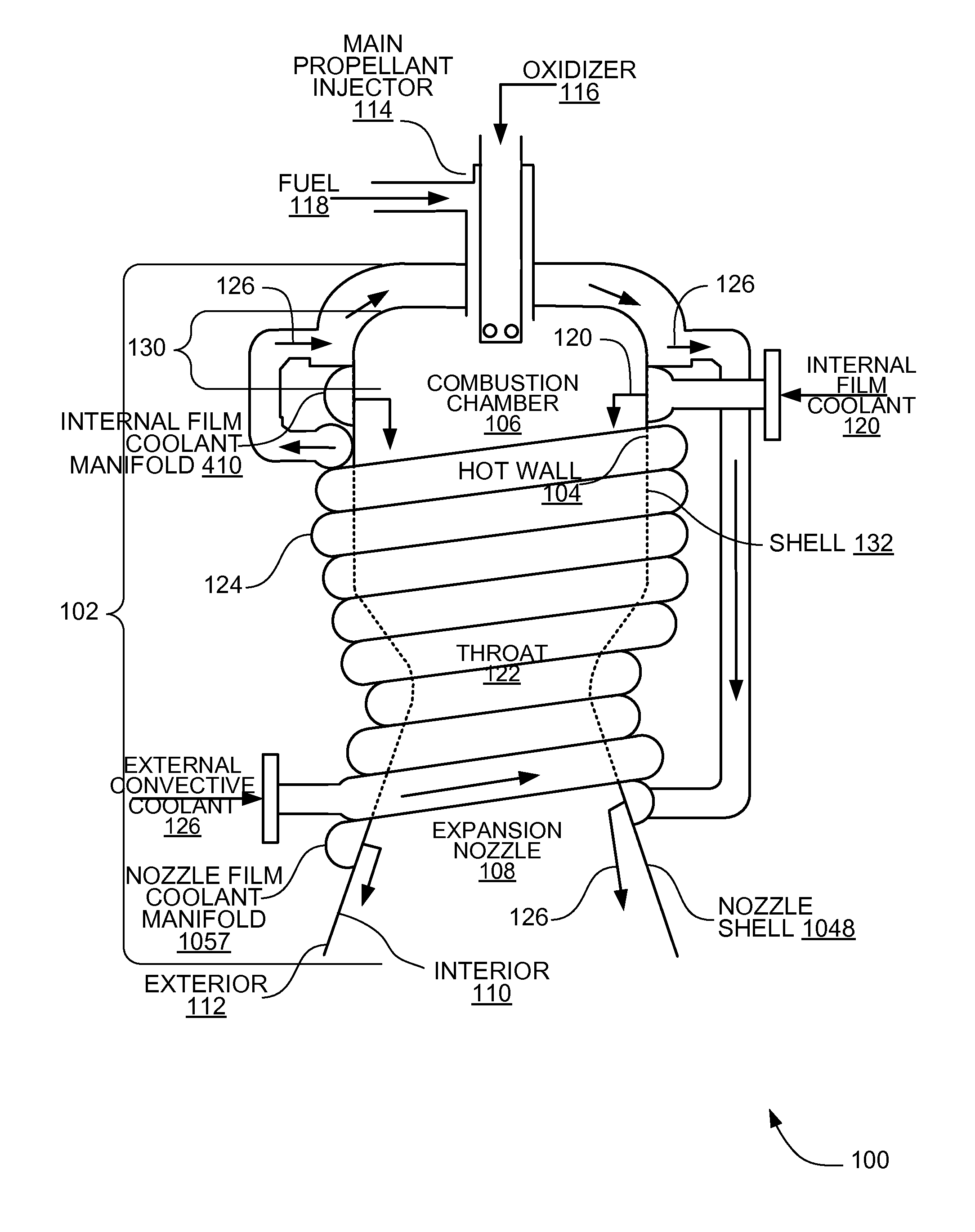
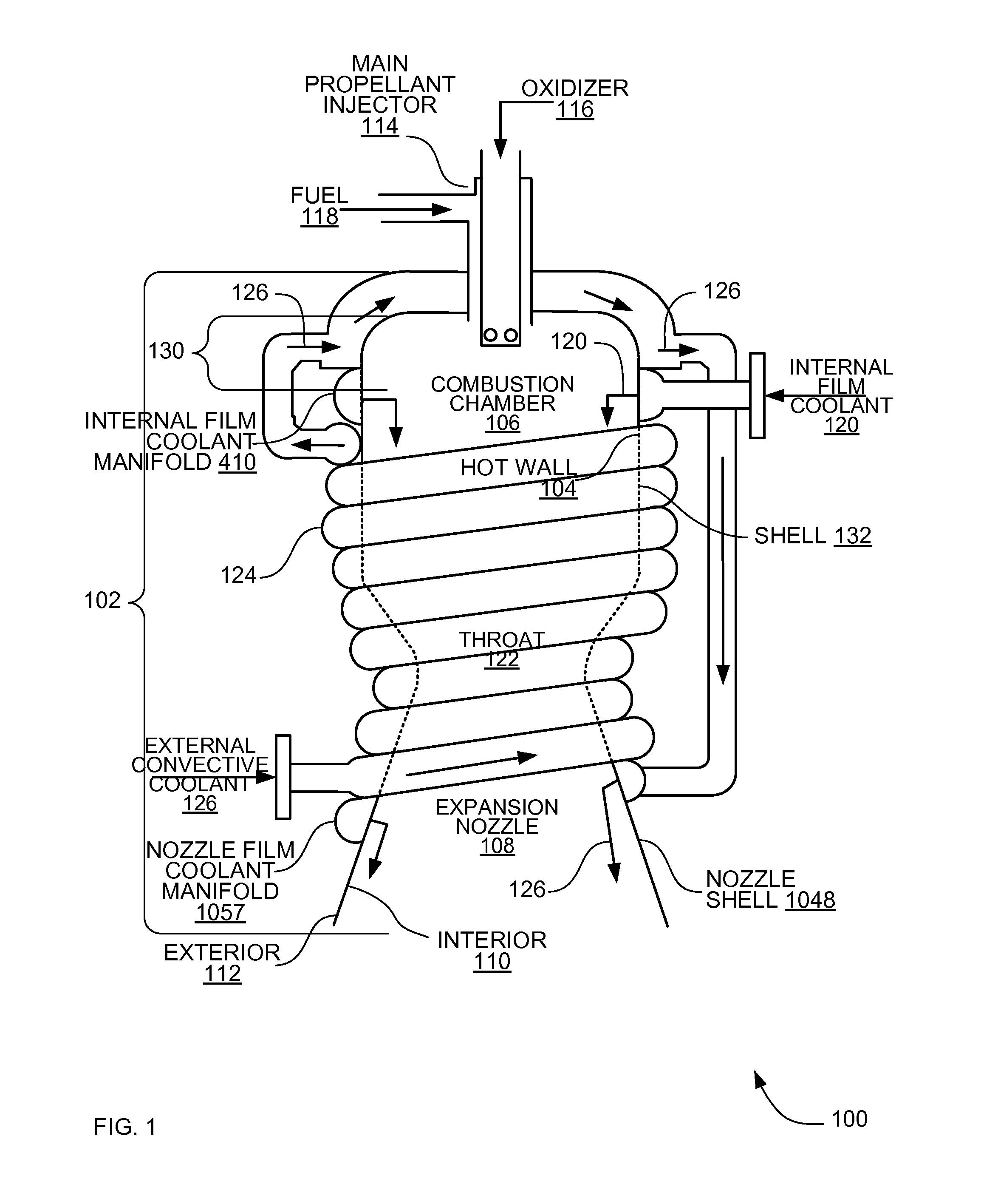
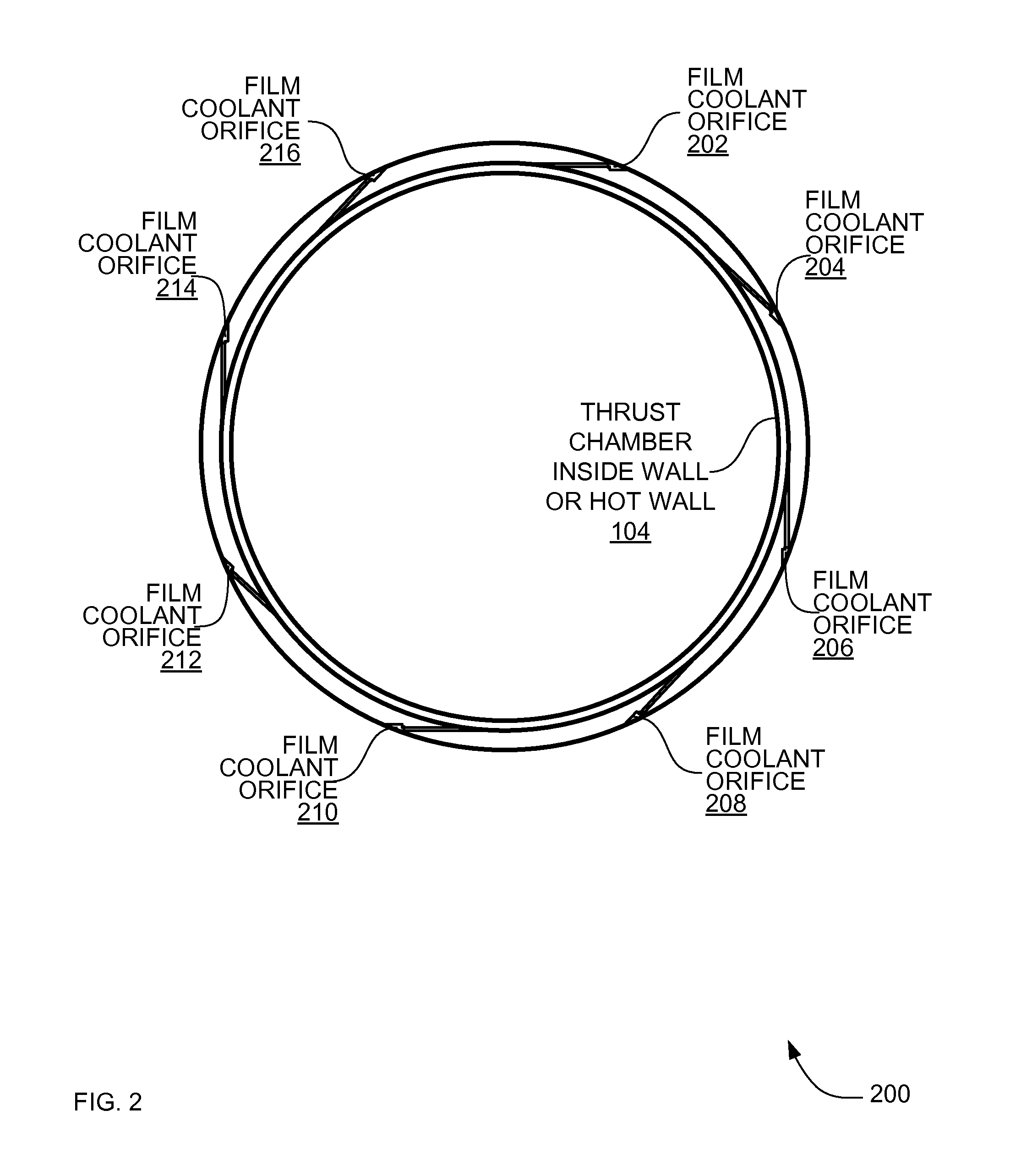
In some implementations a propulsion system includes a thrust chamber comprised of a combustion chamber and an expansion nozzle. The thrust chamber has an interior and exterior surfaces and a main propellant injector mounted to the thrust chamber to inject an oxidizer and a fuel into the interior of the thrust chamber. The total fluid flowing to the rocket engine is compromised of oxidizer, fuel, internal film coolant, and external convective coolant. The internal film coolant ranges from about 1% to about 10% of the total fluid. Reduced coolant tubing circumscribes the exterior of the thrust chamber to circulate an external convective coolant, and a nozzle film coolant manifold mounted to the expansion nozzle injects the external convective coolant onto the interior wall of the expansion nozzle, the external convective coolant being about 1% to about 10% of the total fluid flow to the thrust chamber.

Description

RELATED APPLICATION[0001]This disclosure claims the benefit of U.S. Provisional Application Ser. No. 60 / 833,198 filed Jul. 24, 2006 under 35 U.S.C. 119(e). This disclosure claims priority under 35 U.S.C. 120 to copending U.S. application Ser. No. 11 / 782,631, filed Jul. 24, 2007 entitled “SYSTEMS, METHODS AND APPARATUS FOR PROPULSION.” This disclosure claims the benefit of copending U.S. Provisional Application Ser. No. 61 / 128,761 filed 23 May 2008 under 35 U.S.C. 119(e).FIELD[0002]This disclosure relates generally to propulsion systems, and more particularly to rocket engines.BACKGROUND[0003]In conventional liquid propellant rocket engines, a main propellant injector sprays liquid propellants into a combustion chamber, where the propellants are burned. The burned propellants expand in an expansion nozzle, where the propellants increase in velocity and produce thrust. A thrust chamber encompasses both the combustion chamber and the expansion nozzle.[0004]One of the propellants (usual...

Claims


Application Information

Patent Timeline
Patent Type & Authority Applications(United States)
IPC IPC(8): F02K9/64
CPCF02K9/64F02K9/972F02K9/974F05D2260/202F05D2300/1723F05D2300/171F05D2300/121F05D2300/1721F05D2260/205
Inventor GROTE, JAMES ROBERTPAVIA, THOMAS CLAYTON
Owner GROTE JAMES ROBERT
Learn More