
Input/Output Module and Overall Temperature Control of Samples

a sample and module technology, applied in the field of automatic storage and retrieval systems, can solve problems such as the temperature rise among other samples stored in the system, and achieve the effect of facilitating the transfer of storage cassettes

Inactive Publication Date: 2012-03-15
HAMILTON STORAGE TECH
View PDF0 Cites 52 Cited by
  • Summary
  • Abstract
  • Description
  • Claims
  • Application Information

AI Technical Summary

Benefits of technology

[0010]Another advantage of the invention is that the storage cassettes for long term storage of the samples can also, in the preferred system, fit into the sleeves in the input / output module, thereby enabling the storage cassettes to be removed from the system for maintenance of the storage cassettes or to substitute storage cassettes in the system with cassettes sized for different storage racks or plates. In the exemplary embodiment, shields cover the top and lower portion of the sleeves, but these sleeves can be made removable to facilitate the transfer of a storage cassette into and out of the system through the input / output module.
[0011]It should also be noted that the storage cassettes in some systems can be shorter than about 6 feet tall, for example about 3½ feet tall. In such a system, the input / output cassette described above does not require an upper portion that is not intended to hold sample storage tube racks or plates, but may very well include a lower portion that is not intended to hold sample tube racks or plates.
[0012]Other features and advantages of the invention may be apparent to those skilled in the art upon reviewing the following drawings and description thereof.

Problems solved by technology

The inventors have discovered that introducing warm samples into the system, for example when samples arrive from a processing laboratory, can cause temperature rise among other samples stored in the system unless steps are taken to eliminate or mitigate the temperature rise.

Method used


Image

  • Input/Output Module and Overall Temperature Control of Samples
  • Input/Output Module and Overall Temperature Control of Samples
  • Input/Output Module and Overall Temperature Control of Samples

Examples


Embodiment Construction

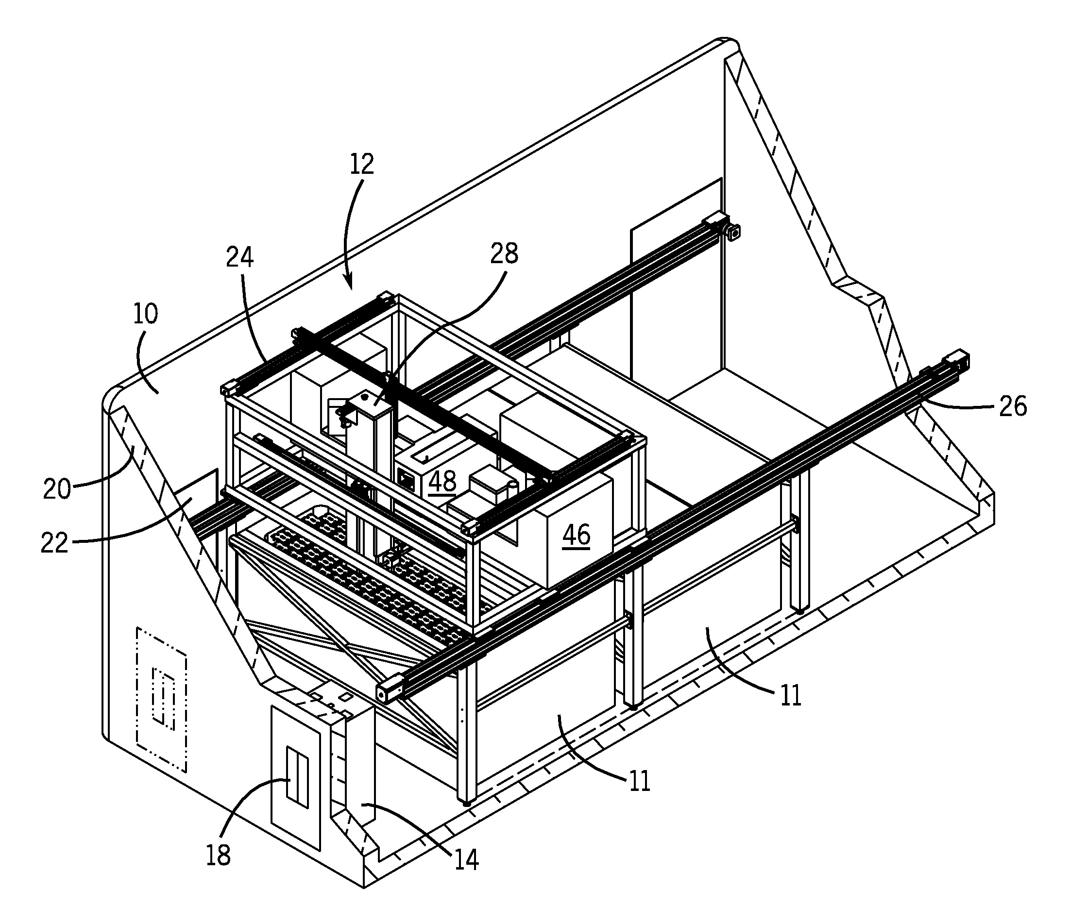
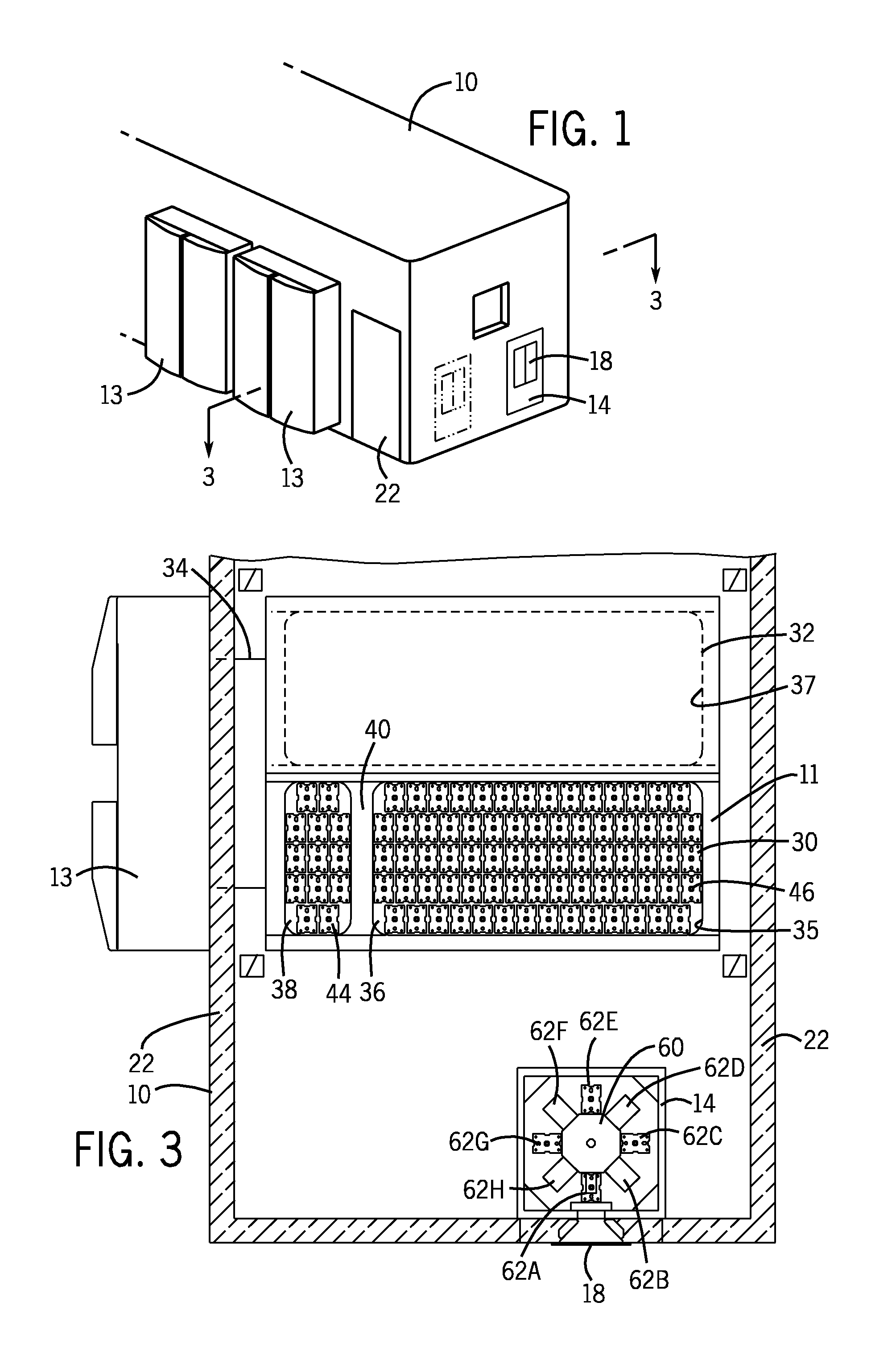
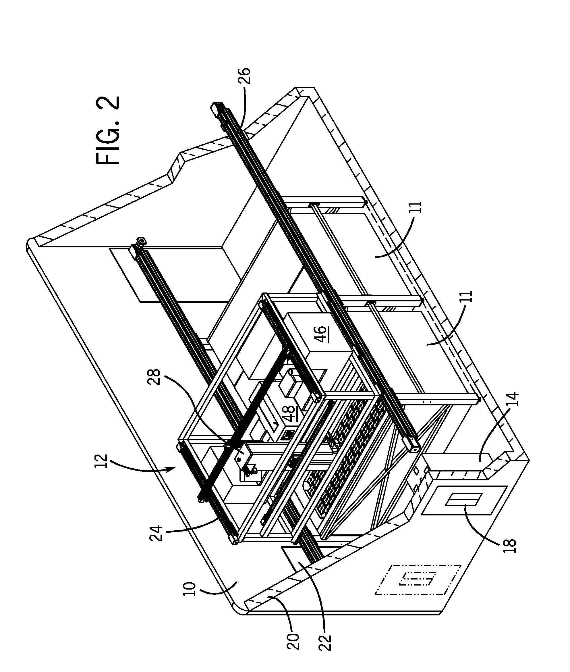
[0027]FIG. 1 illustrates the outside of a refrigerated enclosure 10 maintained at a temperature of approximately −15° C. to −30° C., preferably about −20° C. FIG. 2 shows an automated storage and retrieval system 12 for storing sample tube racks or plates at an ultra-low or cryogenic temperature located within the refrigerated enclosure 10. A sample input / output module 14 is located inside the refrigerated enclosure 10 along its front wall adjacent an opening 16 (FIG. 3) covered by a door 18 or a set of doors. FIGS. 1 and 2 illustrate in phantom that it may desirable for the system to include a second input / output module. In FIGS. 1 and 2, the input / output modules are located along a front wall 20 of the refrigerated enclosure 10, however depending on the application it may desirable to locate the input / output module 14 along a sidewall 22 of the refrigerated enclosure 10, for example in the location of the full length door shown in FIGS. 1 and 2. Multiple horizontal freezer chests ...


PUM


Abstract

An automated storage and retrieval system for storing chemical and biological samples includes freezer chests maintained at an ultra-low temperature (e.g. −80° C.) or a cryogenic temperature. The freezer chests are located within a refrigerated (e.g. −20° C.) enclosure. Samples are loaded through a wall of the enclosure and are then transferred to an input / output buffer section in an ultra-low temperature or cryogenic freezer chest that is thermally segregated from a long-term storage section in the same freezer. Specialized input / output cassettes are used for transferring the samples through an input / output module into the system.

Description

CROSS REFERENCE TO RELATED APPLICATIONS[0001]This application claims priority to U.S. Provisional Patent Application No. 61 / 381,832, filed on Sep. 10, 2010 entitled “Large Automated Storage and Retrieval System for Storing Biological or Chemical Samples at Ultra-Low or Cryogenic Temperatures”.FIELD OF THE INVENTION[0002]The invention relates to automated storage and retrieval systems for ultra-low temperature or cryogenic freezer systems used primarily to store biological or chemical samples. In particular, the present invention pertains to systems and methods for efficiently inputting and retrieving samples from the freezers without causing significant temperature rise of other samples stored within the system.BACKGROUND OF THE INVENTION[0003]Storage of biological and chemical samples is becoming widespread in the biotechnology and medical industries. To preserve many of these samples, the samples must be stored well below normal freezing temperatures. Generally speaking, a regular...

Claims


Application Information

Patent Timeline
IPC IPC(8): F25D25/00
CPCA01N1/0236G01N2035/0462B01L7/50B01L9/06B01L2200/026B01L2200/04B01L2300/021B01L2300/04B65G1/00F17C3/085F25D25/00F25D25/04G01N1/42G01N35/0099G01N35/04G01N2035/00346G01N2035/00435G01N2035/042G01N2035/0425A01N1/0252
Inventor COLLINS, SCOTTHUNT, FRANKWARHURST, JULIANZANDI, BRUCE
Owner HAMILTON STORAGE TECH
Learn More