Energy recovery system for an internal combustion engine arrangement, comprising thermoelectric devices

Inactive Publication Date: 2012-03-15
RENAULT TRUCKS
View PDF11 Cites 8 Cited by
  • Summary
  • Abstract
  • Description
  • Claims
  • Application Information

AI Technical Summary

Benefits of technology

[0018]According to an embodiment of the invention, the system comprises a secondary line having an inlet connected to the main line between the first and the second thermoelectric devices and an outlet connected to the main line downstream from said second thermoelectric device, the system further comprising a valve capable of directing one part of the exhaust gases flowing in the main line towards the second thermoelectric device and the other part of said exhaust gases towards the secondary line. Said secondary line can comprise a secondary thermoelectric device capable of producing electricity by Seebeck effect by the conversion of a heat flux between the hot exhaust gases flowing in the secondary line and a cold source, said secondary thermoelectric device having an optimum temperature range and a highest admissibl

Problems solved by technology

However, one important limit of this conventional system is that the flow rate and temperature of the exhaust gases can vary in a quite wide range, depending on the engine operating conditions.
As a consequence, the efficiency of the thermoelectric device can be poor, when the exhaust gases temperature is far from the optim

Method used


Image

  • Energy recovery system for an internal combustion engine arrangement, comprising thermoelectric devices
  • Energy recovery system for an internal combustion engine arrangement, comprising thermoelectric devices

Examples


third embodiment

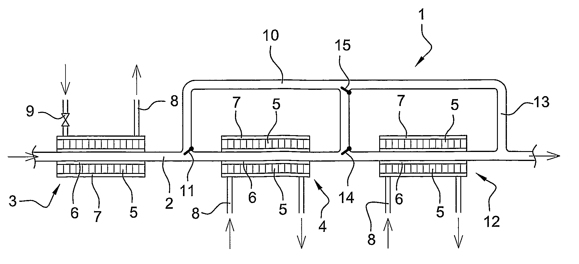
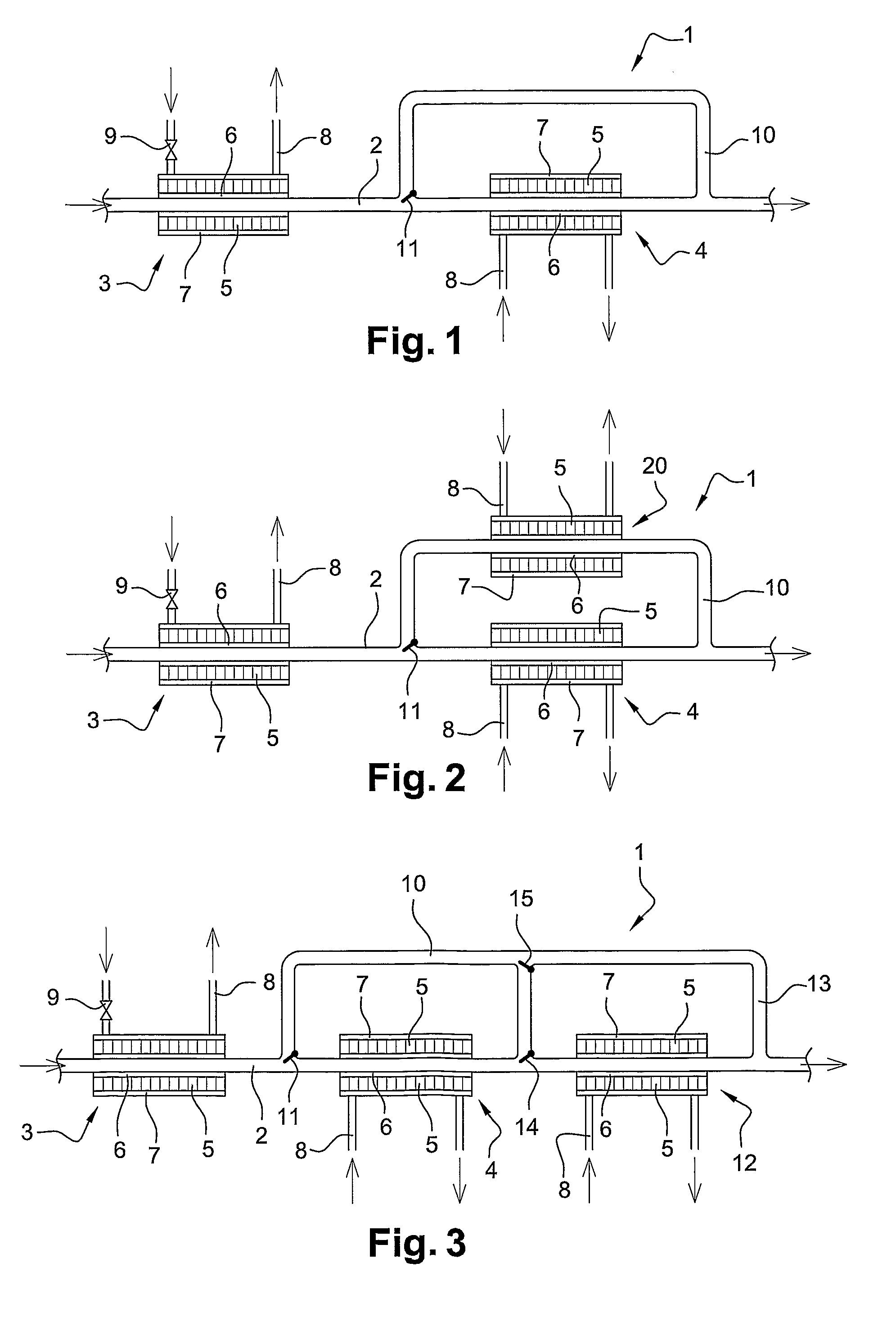
[0043]the invention is illustrated in FIG. 3. A first, second and third thermoelectric devices 3, 4, 12 are successively provided on the main line 2. These devices have decreasing optimum temperature ranges and highest admissible temperatures from the first one to the third one.

[0044]Furthermore, the exhaust line 1 includes an additional branch 13 having an inlet connected to the secondary line 10 and an outlet connected to the main line 2 downstream from the third thermoelectric device 12. Valves 14, 15 are provided respectively at the downstream junction between the main line 2 and the secondary line 10, and at the junction between the additional branch 13 and the secondary line 10. The first thermoelectric device 3 is exposed to the exhaust gases at all times. Depending on the exhaust gases temperature and / or flow rate, the second and / or third thermoelectric devices 4, 12 are exposed on not to these gases, to protect them from overheating. The second and third thermoelectric devi...

second embodiment

[0045]Similarly with FIG. 2, it would also be possible to provide additional thermoelectric devices with appropriate optimum temperature ranges and highest admissible temperatures on the secondary line 10 and / or on the additional branch 13.


PUM


Abstract

An energy recovery system includes a main line capable of carrying the exhaust gases of an engine, at least a first and a second thermoelectric devices capable of producing electricity by Seebeck effect, the second thermoelectric device being located downstream from the first thermoelectric device, the thermoelectric devices each having an optimum temperature range and a highest admissible temperature. The optimum temperature range and the highest admissible temperature of the second thermoelectric device are lower than the optimum temperature range and the highest admissible temperature of the first thermoelectric device, respectively. The system further includes a controller for controlling the flow rate of the exhaust gases passing against the second thermoelectric device, in order to prevent the second thermoelectric device from being exposed to temperatures exceeding its highest admissible temperature.

Description

BACKGROUND AND SUMMARY[0001]The present invention relates to an internal combustion engine arrangement for an automotive vehicle, especially an industrial vehicle. More specifically, the invention relates to an energy recovery system for such an engine arrangement.[0002]A conventional internal combustion engine arrangement comprises an exhaust line capable of collecting exhaust gas from the engine, for example through an exhaust manifold. A significant amount of energy is included in said exhaust gases, which have a high speed and a high temperature.[0003]Several systems have been designed to recover at least part of this energy, in order to improve the vehicle efficiency, more particularly the engine arrangement efficiency, which has a direct impact on fuel consumption. One conventional system consists of equipping the exhaust line with one or several thermoelectric devices using the Seebeck effect. Such a thermoelectric device is capable of producing electricity by the conversion ...

Claims


Application Information

Patent Timeline
IPC IPC(8): F02B63/00
CPCF01N5/025F01N11/002F01N2240/36F01N2410/02F01N13/009Y02T10/16Y02T10/166Y02T10/47H01L35/30Y02T10/12Y02T10/40H10N10/13
Inventor AIXALA, LUC
Owner RENAULT TRUCKS
Why Eureka
Try Eureka