
Pneumatic tire

a technology of pneumatic tires and treads, applied in the field of pneumatic tires, can solve the problems of increased wear, decreased durability, and abnormal wear and cracking of the tread surface, and achieve the effect of steering stability, desired tire performance, and steering stability

Inactive Publication Date: 2012-03-15
YOKOHAMA RUBBER CO LTD
View PDF10 Cites 17 Cited by
  • Summary
  • Abstract
  • Description
  • Claims
  • Application Information

AI Technical Summary

Benefits of technology

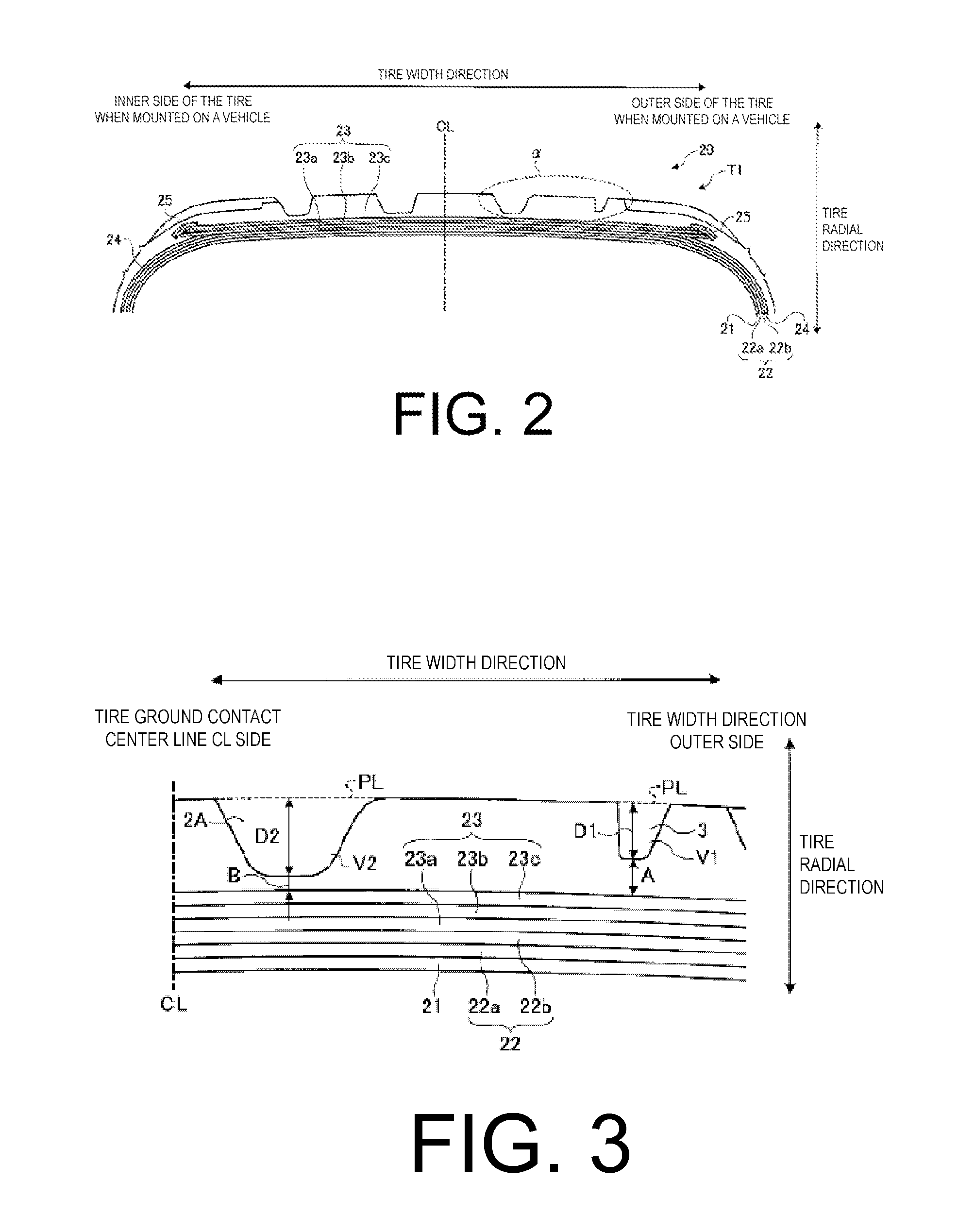
[0008]The present technology provides a pneumatic tire in which steering stability on dry road surfaces and durability can be enhanced while a decline in steering stability on wet road surfaces is suppressed. A pneumatic tire (type 1) includes an asymmetrical pattern wherein groove area ratios with respect to a tread ground contact area in a first side in a tire width direction and in a second side in the tire width direction, demarcated by a tire ground contact center line, vary in a range of not less than 5% and not more than 15%. The side from the tire ground contact center line having a smaller groove area ratio includes at least one circumferential main groove and at least one circumferential narrow groove that is positioned on an outer side in the tire width direction of the circumferential main groove. A depth of the circumferential narrow groove is not less than 60% and not more than 80% of a depth of the circumferential main groove closest to the tire ground contact center line. A width of the circumferential narrow groove is not less than 25% and not more than 40% of a width of the circumferential main groove closest to the tire ground contact center line. A distance from the tire ground contact center line to a center position in the tire width direction of the circumferential narrow groove is not less than 25% and not more than 35% of a tire ground contact width.
[0009]This pneumatic tire includes an asymmetrical pattern wherein groove area ratios with respect to a tread ground contact area in a first side in a tire width direction and in a second side in the tire width direction, demarcated by a tire ground contact center line, vary in a range of not less than 5% and not more than 15%. This configuration is used primarily for the purpose of providing more land portions on the outer side of the tire when mounted on a vehicle, which is subjected to a relatively greater amount of wear when high-speed running or circuit running, thus relatively increasing the stiffness of the outer side of the tire when mounted on a vehicle.

Problems solved by technology

Additionally, with pneumatic tires having the configuration described above, there is a risk of abnormal wear and cracking occurring in the tread surface of an outer side of the tire when mounted on a vehicle after high-speed running or circuit running, and there is also a risk of durability declining.
This configuration is used primarily for the purpose of providing more land portions on the outer side of the tire when mounted on a vehicle, which is subjected to a relatively greater amount of wear when high-speed running or circuit running, thus relatively increasing the stiffness of the outer side of the tire when mounted on a vehicle.

Method used


Image

  • Pneumatic tire
  • Pneumatic tire
  • Pneumatic tire

Examples


embodiment 1

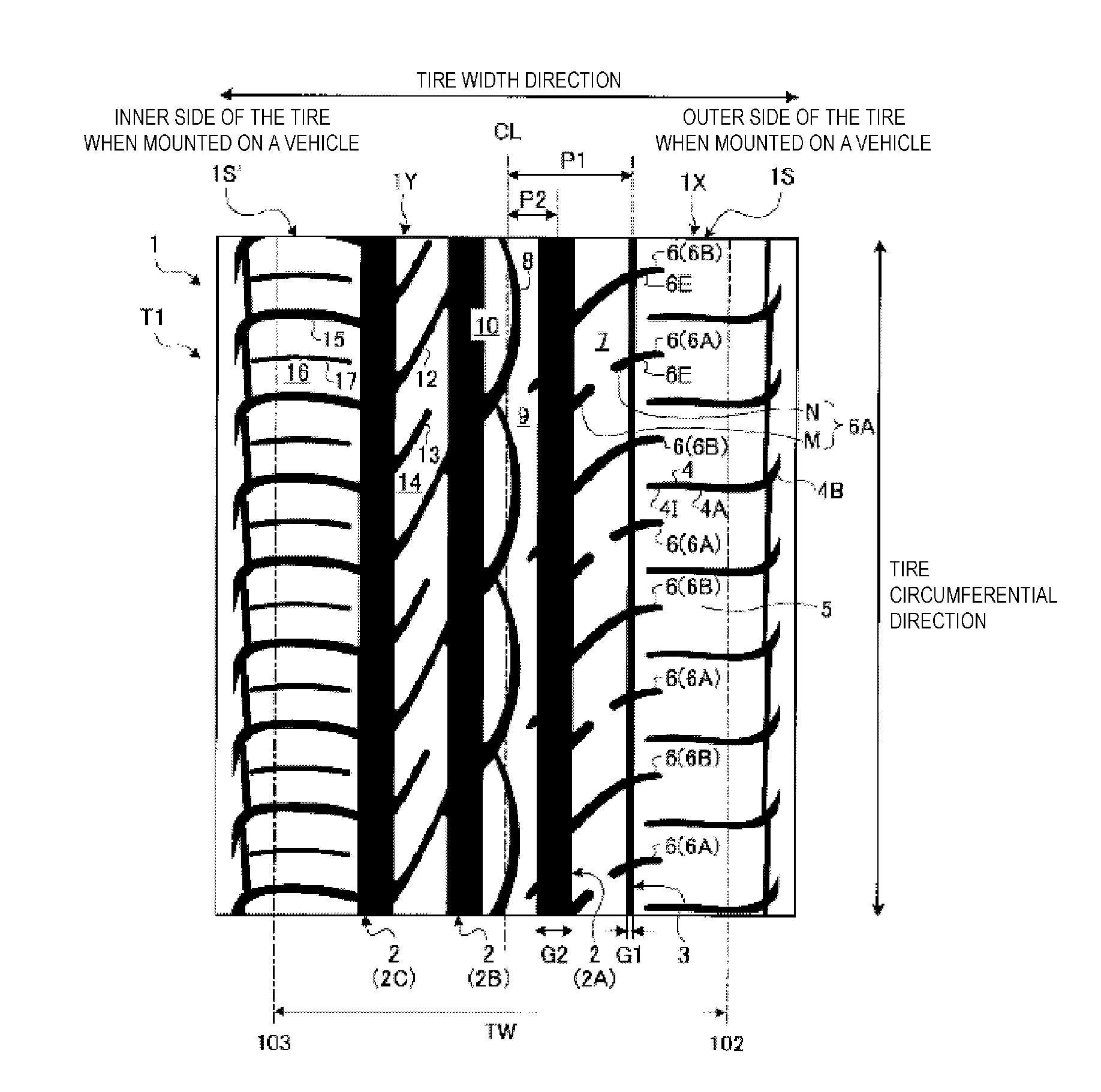
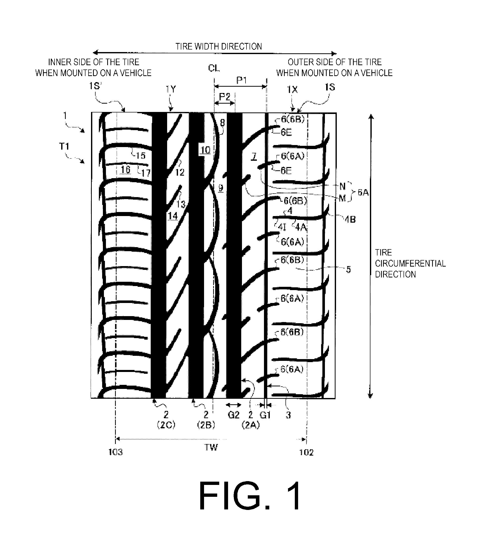
[0035]FIG. 1 is a plan view illustrating a tread surface of a pneumatic tire of embodiment 1. A pneumatic tire T1 illustrated in FIG. 1 has a designated mounting direction when mounted on a vehicle, and is configured so that the side right of a tire ground contact center line CL is the outer side of the tire when mounted on a vehicle. Here, “tire ground contact center line CL” refers to a center line in the tire width direction in a tread contact patch when the pneumatic tire T1 is assembled on a regular rim, inflated to a regular pressure, and when loaded with a designated load. “Regular rim” refers to a “standard rim” defined by JATMA, a “Design Rim” defined by the Tire and Rim Association, Inc. (TRA), or a “Measuring Rim” defined by the European Tyre and Rim Technical Organisation (ETRTO). “Regular inner pressure” refers to the “maximum air pressure” defined by JATMA, the maximum value in “tire load limits at various cold inflation pressures” defined by TRA, and the “inflation pr...

embodiment 2

[0068]Next, a description of Embodiment 2 will be given. Embodiment 2 differs from Embodiment 1 in that a circumferential main groove is positioned on the tire ground contact center line CL.

[0069]FIG. 4 is a plan view illustrating a tread surface of a pneumatic tire of embodiment 2. Only the differences from the example illustrated in FIG. 1 (Embodiment 1) will be described for the example illustrated in FIG. 4 (Embodiment 2). Note that in FIG. 4, those constituents that have the same reference numerals as in FIG. 1 are identical to the constituents illustrated in FIG. 1.

[0070]In the pneumatic tire T2 illustrated in FIG. 4, four circumferential main grooves 2 extending linearly in the tire circumferential direction are provided in a tread surface 31. The tread surface 31 includes an outer side region 1X positioned outward of the tire ground contact center line CL when the tire is mounted, and an inner side region 1Y positioned inward of the tire ground contact center line CL when th...

examples

[0083]Pneumatic tires according to the embodiments, conventional example, and comparative examples were manufactured and evaluated. Note that the pneumatic tires according to the embodiments are working examples. The comparative examples are not the same as the conventional example.


PUM


Abstract

A pneumatic tire wherein a side from a tire ground contact center line having a smaller groove area ratio includes at least one circumferential main groove and at least one circumferential narrow groove. A depth of the circumferential narrow groove is not less than 60% and not more than 80% of a depth of the circumferential main groove closest to the tire ground contact center line. A width of the circumferential narrow groove is not less than 25% and not more than 40% of a width of the circumferential main groove closest to the tire ground contact center line. A distance from the tire ground contact center line to a center position in the tire width direction of the circumferential narrow groove is not less than 25% and not more than 35% of a tire ground contact width.

Description

PRIORITY CLAIM[0001]Priority is claimed to Japan Patent Application Serial No. 2010-202417 filed on Sep. 9, 2010.BACKGROUND[0002]1. Technical Field[0003]The present technology relates to a pneumatic tire, and more particularly relates to a pneumatic tire whereby steering stability on dry road surfaces can be enhanced and durability can be enhanced.[0004]2. Related Art[0005]Conventionally, pneumatic tires having a designated tire mounting direction are known in which a first lateral groove is distanced from a circumferential narrow groove, and a land portion outward in the tire width direction of the circumferential narrow groove is formed into a rib. Additionally, the first lateral groove is formed by contiguously connecting a first arcuate groove portion, which is convex toward a first side in the tire circumferential direction, and a second arcuate groove portion, which is convex toward a second side in the tire circumferential direction (e.g. see Japanese Unexamined Patent Applic...

Claims


Application Information

Patent Timeline
IPC IPC(8): B60C11/117
CPCB60C11/0306B60C2011/0381B60C11/033B60C11/0304
Inventor NEMOTO, MASAYUKI
Owner YOKOHAMA RUBBER CO LTD
Learn More