Shock absorber

a shock absorber and shock absorber technology, applied in the direction of shock absorbers, vibration dampers, springs/dampers, etc., can solve the problems of inability to variably control the damping force generated in high-frequency mode and low-frequency mode, and the conventional shock absorber has a limitation in improving ride comfort, so as to ensure steering stability

Active Publication Date: 2015-06-11
HL MANDO CORP
View PDF2 Cites 2 Cited by
  • Summary
  • Abstract
  • Description
  • Claims
  • Application Information

AI Technical Summary

Benefits of technology

The present invention is a shock absorber that uses a pilot valve and controls a variable frequency characteristic to provide a round ride comfort and damping feeling. It also ensures steering stability through a linear vehicle control. The guide member is opened in the high-frequency mode to reduce damping force, while it is prevented from being opened in the low-frequency mode to generate a main damping force through the first pressure chamber, the second pressure chamber, and the fourth pressure chamber.

Problems solved by technology

In the case of a high functional damper (HFD), a conventional shock absorber is effective in a high-speed degressive characteristic and an ultra-low-speed tuning, but cannot variably control a damping force generated in a high-frequency mode and a low-frequency mode.
Hence, the conventional shock absorber has a limitation in improving a ride comfort.

Method used


Image

  • Shock absorber
  • Shock absorber
  • Shock absorber

Examples


Embodiment Construction

[0021]Hereinafter, a shock absorber according to a preferred embodiment of the present invention will be described with reference to the accompanying drawings.

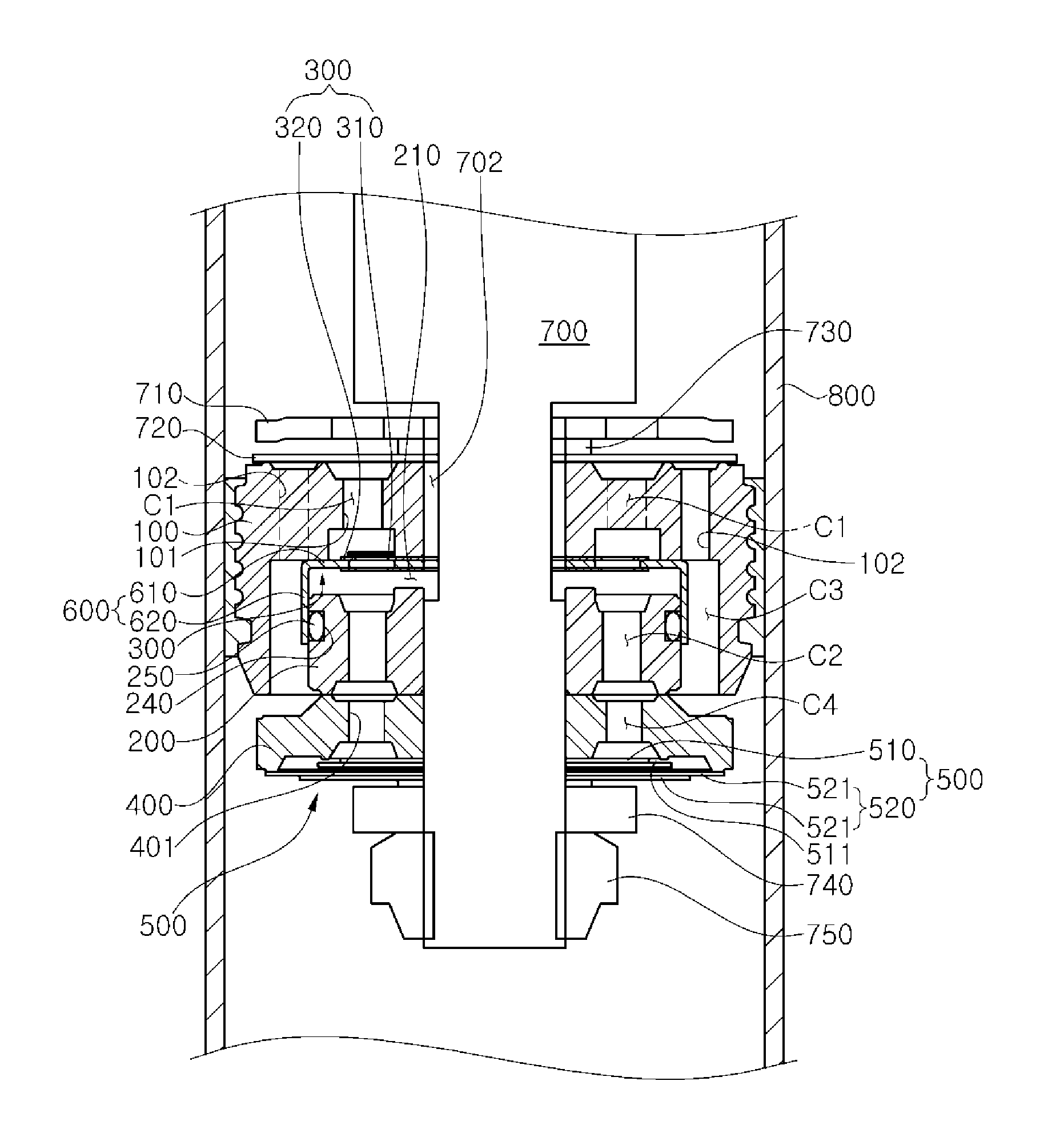
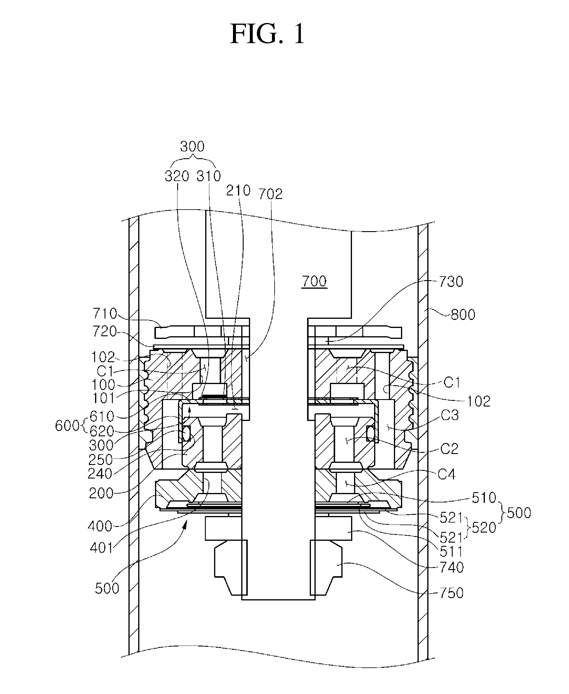
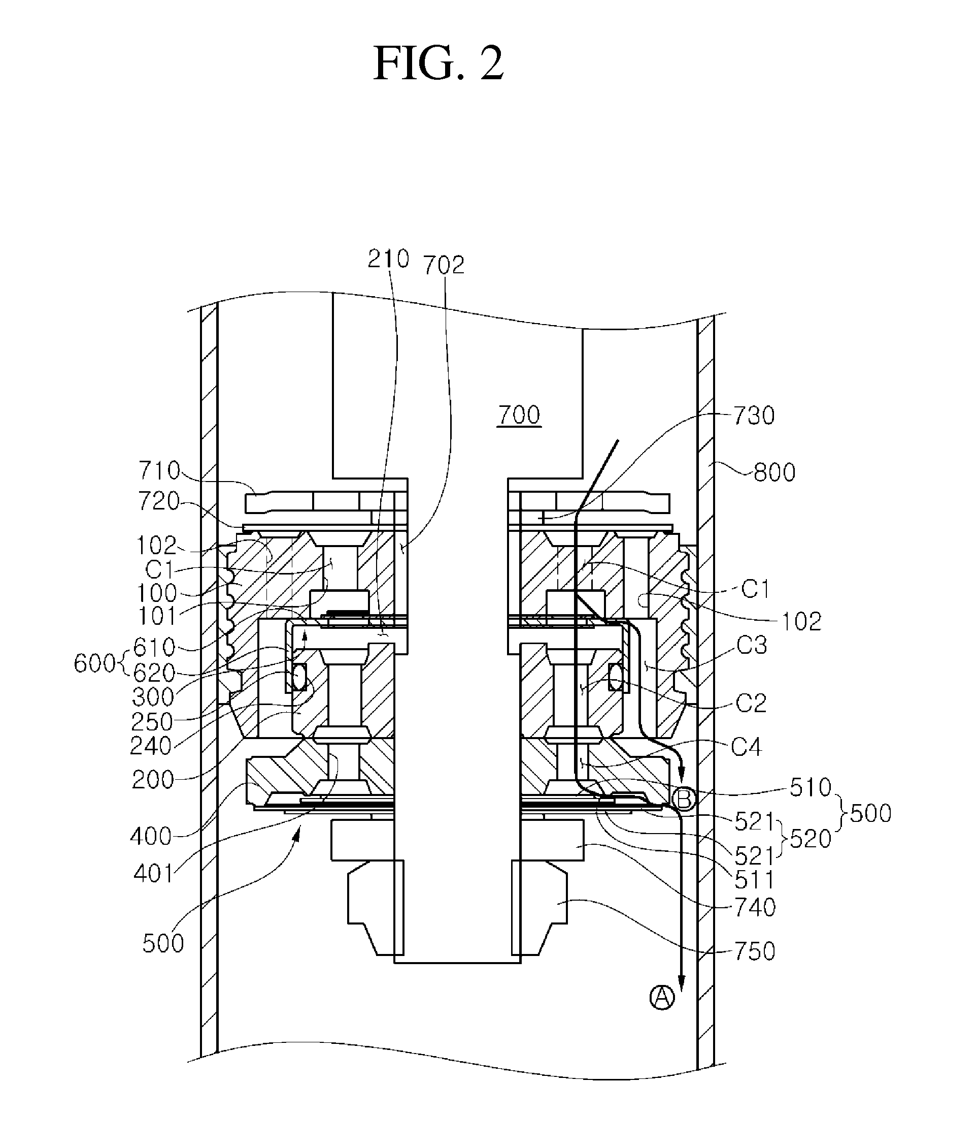
[0022]FIG. 1 is a cross-sectional conceptual diagram illustrating an overall configuration of a shock absorber according to an embodiment of the present invention, FIG. 2 is a cross-sectional conceptual diagram illustrating a flow of a working fluid in a high-frequency mode (a small-amplitude mode) during a rebound stroke in the shock absorber according to the embodiment of the present invention, and FIG. 3 is a cross-sectional conceptual diagram illustrating a flow of a working fluid in a low-frequency mode (a large-amplitude mode) during a rebound stroke in the shock absorber according to the embodiment of the present invention.

[0023]Referring to FIGS. 1 to 3, the shock absorber according to the preferred embodiment of the present invention includes a piston rod 700, a first piston 100, a pilot valve 300, a second piston (lo...


PUM


Abstract

In a high-frequency mode (a small-amplitude mode), a shock absorber opens a guide member to reduce a damping force. In a low-frequency mode (a large-amplitude mode), the shock absorber prevents the guide member from being opened by increasing a pressure of a second pressure chamber formed between a second piston (lower piston) and a pilot valve through a groove (passage) formed in an outer periphery of a piston rod. A main damping force is generated through the second pressure chamber and a disk valve assembly. Therefore, it is possible to provide a round ride comfort having a damping feeling and ensure a steering stability through a linear vehicle control.

Description

[0001]CROSS-REFERENCE(S) TO RELATED APPLICATION[0002]This application claims priority of Korean Patent Application No. 10-2013-0152412, filed on Dec. 9, 2013, in the Korean Intellectual Property Office, the contents of which are incorporated herein by reference in its entirety.BACKGROUND OF THE INVENTION[0003]1. Field of the Invention[0004]The present invention relates to a shock absorber, and more particularly, to a shock absorber which is capable of achieving a pressure-sensitive characteristic by using a pilot valve and controlling a variable frequency characteristic, which is input from a road surface, through a lateral passage formed by an open of a guide member.[0005]2. Description of the Related Art[0006]Generally, a shock absorber is designed to support a weight of a vehicle body and suppress and dampen a vibration transferred from a road surface to the vehicle body, contributing to improving a ride comfort and protecting loaded goods and various parts of a vehicle.[0007]Suc...

Claims


Application Information

Patent Timeline
IPC IPC(8): F16F9/512F16F9/348
CPCF16F9/512F16F9/348F16F9/5126
Inventor KIM, TAE JU
Owner HL MANDO CORP
Why Eureka
Try Eureka