
Display operable in both reflective and transmissive modes

a display and transmittance technology, applied in the field of flat panel displays, can solve the problems of low light use efficiency of the transmittance display apparatus, and achieve the effects of reducing power consumption, improving light use efficiency, and reducing parallax phenomenon

Active Publication Date: 2012-03-15
PUSAN NAT UNIV IND UNIV COOPERATION FOUND +1
View PDF6 Cites 39 Cited by
  • Summary
  • Abstract
  • Description
  • Claims
  • Application Information

AI Technical Summary

Benefits of technology

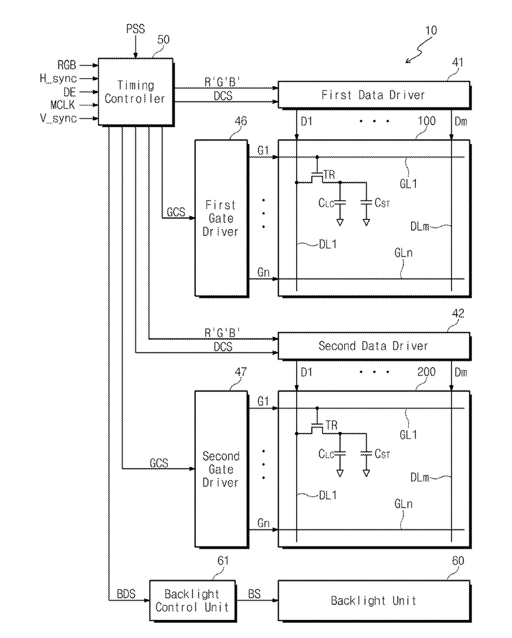
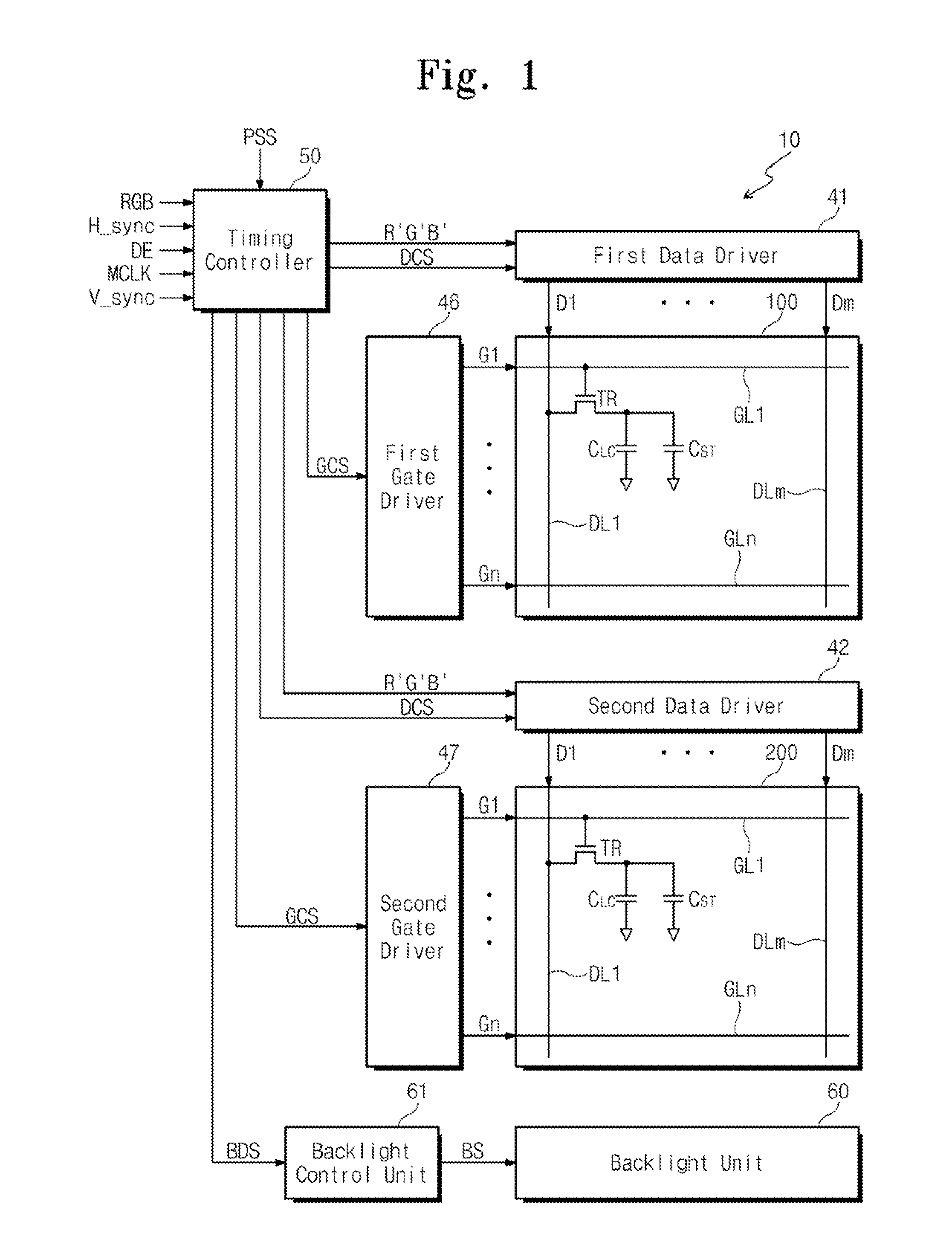
[0009]Exemplary embodiments of the present invention provide a display apparatus capable of being used as a transmissive type or a reflective type while having improved display characteristics.
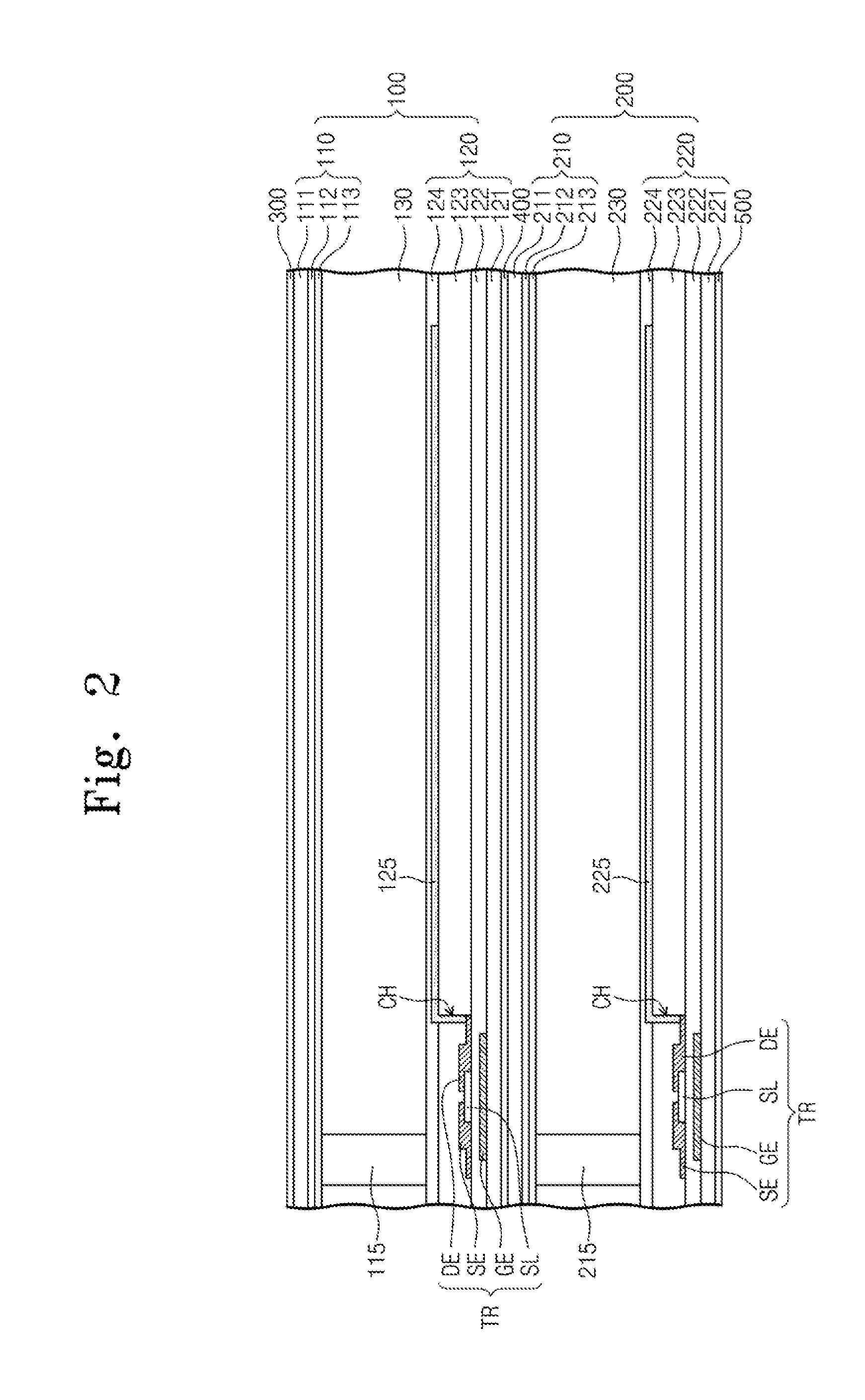
[0016]As described above, the image can be displayed through the first display panel when the display apparatus is used in reflective mode, and can be displayed through the second display panel when the display apparatus is used in transmissive mode. Accordingly, light use efficiency can be increased, and power consumption can be reduced. When the display apparatus is used in the reflective mode, the first display panel is utilized, so that a parallax phenomenon can be reduced.

Problems solved by technology

Accordingly, the transflective display apparatus has low efficiency of using light when the transflective display apparatus is used in a transmissive mode or a reflective mode.

Method used


Image

  • Display operable in both reflective and transmissive modes
  • Display operable in both reflective and transmissive modes
  • Display operable in both reflective and transmissive modes

Examples


Embodiment Construction

[0029]It will be understood that when an element or layer is referred to as being “on”, “connected to” or “coupled to” another element or layer, it can be directly on, connected or coupled to the other element or layer or intervening elements or layers may be present. In contrast, when an element is referred to as being “directly on,”“directly connected to” or “directly coupled to” another element or layer, there are no intervening elements or layers present. Like numbers refer to like elements throughout. As used herein, the term “and / or” includes any and all combinations of one or more of the associated listed items.

[0030]It will be understood that, although the terms first, second, etc. may be used herein to describe various elements, components, regions, layers and / or sections, these elements, components, regions, layers and / or sections should not be limited by these terms. These terms are only used to distinguish one element, component, region, layer or section from another reg...


PUM

PropertyMeasurementUnit
angleaaaaaaaaaa
wavelengthaaaaaaaaaa

Abstract

A display apparatus includes a first display panel with a plurality of first pixels, a second display panel facing the first display panel and having a plurality of second pixels, a light reflective polarizer, and a backlight unit. The light reflective polarizer is interposed between the first and second display panels to transmit light polarized in a first direction, and reflect light polarized in a second direction substantially perpendicular to the first direction. The backlight unit is arranged proximate to the second display panel to supply light to the first and second display panels. The first display panel displays an image by using reflected ambient light, and the second display panel displays an image by using light from the backlight unit.

Description

CROSS-REFERENCE TO RELATED APPLICATION[0001]This application claims priority to, and the benefit of, Korean Patent Application No. 2010-90188 filed on Sep. 14, 2010, the contents of which are herein incorporated by reference in their entirety.BACKGROUND[0002]1. Field of disclosure[0003]Embodiments of the present invention relate generally to flat panel displays.[0004]More particularly, embodiments of the present invention relate to a display apparatus capable of being used as a transmissive type or a reflective type display.[0005]2. Description of the Related Art[0006]In general, a liquid crystal display (LCD) includes a first substrate, a second substrate facing the first substrate, and a liquid crystal layer interposed between the first and second substrates. The LCD displays an image according to an electric field applied to the liquid crystal layer.[0007]Since liquid crystal contained in the liquid crystal layer is a non-emissive material, a separate light source typically suppl...

Claims


Application Information

Patent Timeline
Patent Type & Authority Applications(United States)
IPC IPC(8): G09G3/36G02F1/1335
CPCG02F2001/133531G02F1/1347G02F1/133531G02F1/13306G02F1/133536G02F1/1336
Inventor CHEONG, BYOUNGHOYOU, JAEHOKIM, TAEWOOKWAK, EUN-AEKIM, JAECHANGYOON, TAEHOONKIM, KIHAN
Owner PUSAN NAT UNIV IND UNIV COOPERATION FOUND
Learn More