Optical device unit and detection apparatus

a detection apparatus and optical device technology, applied in the direction of optical radiation measurement, instruments, spectrometry/spectrophotometry/monochromators, etc., can solve the problems of low detection sensitivity, low signal weak intensity of raman scattering light, so as to efficiently receive raman scattering light

Inactive Publication Date: 2012-03-15
SEIKO EPSON CORP
View PDF3 Cites 4 Cited by
  • Summary
  • Abstract
  • Description
  • Claims
  • Application Information

AI Technical Summary

Benefits of technology

[0036]As a result, it is possible to efficiently receiv...

Problems solved by technology

However, the signal intensity of the Raman scattering light is typically weak, and its detection sensitivity is low.
Depending on the type of target substance, or the type of an optical device, signal int...

Method used


Image

  • Optical device unit and detection apparatus
  • Optical device unit and detection apparatus
  • Optical device unit and detection apparatus

Examples


Embodiment Construction

[0059]Hereinafter, preferable embodiments of the invention will be described in detail. Embodiments of the invention described below are not intended to limit the scope of the invention described in the claims, and all of the configurations described in the embodiments of the invention are not necessarily indispensable as solving means of the invention.

1. Overview

1.1. Basic Configuration

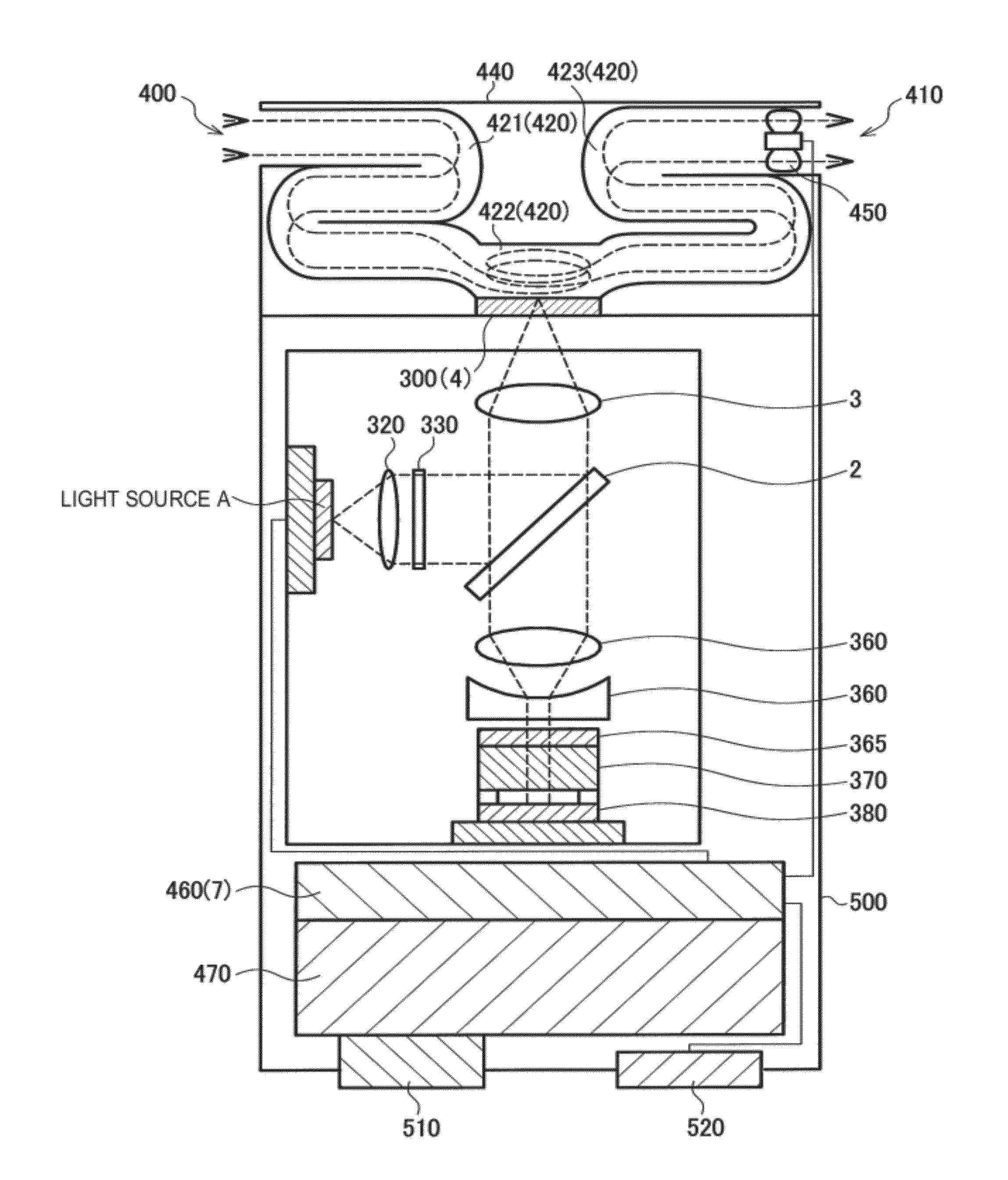
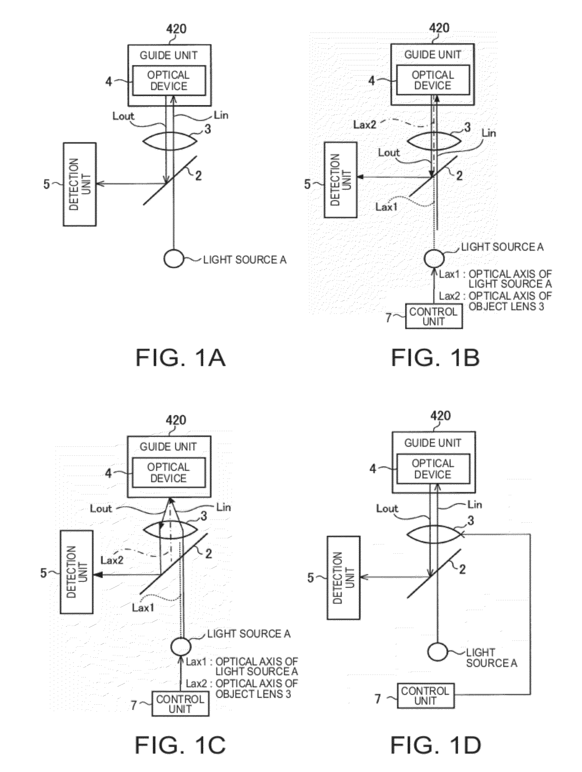
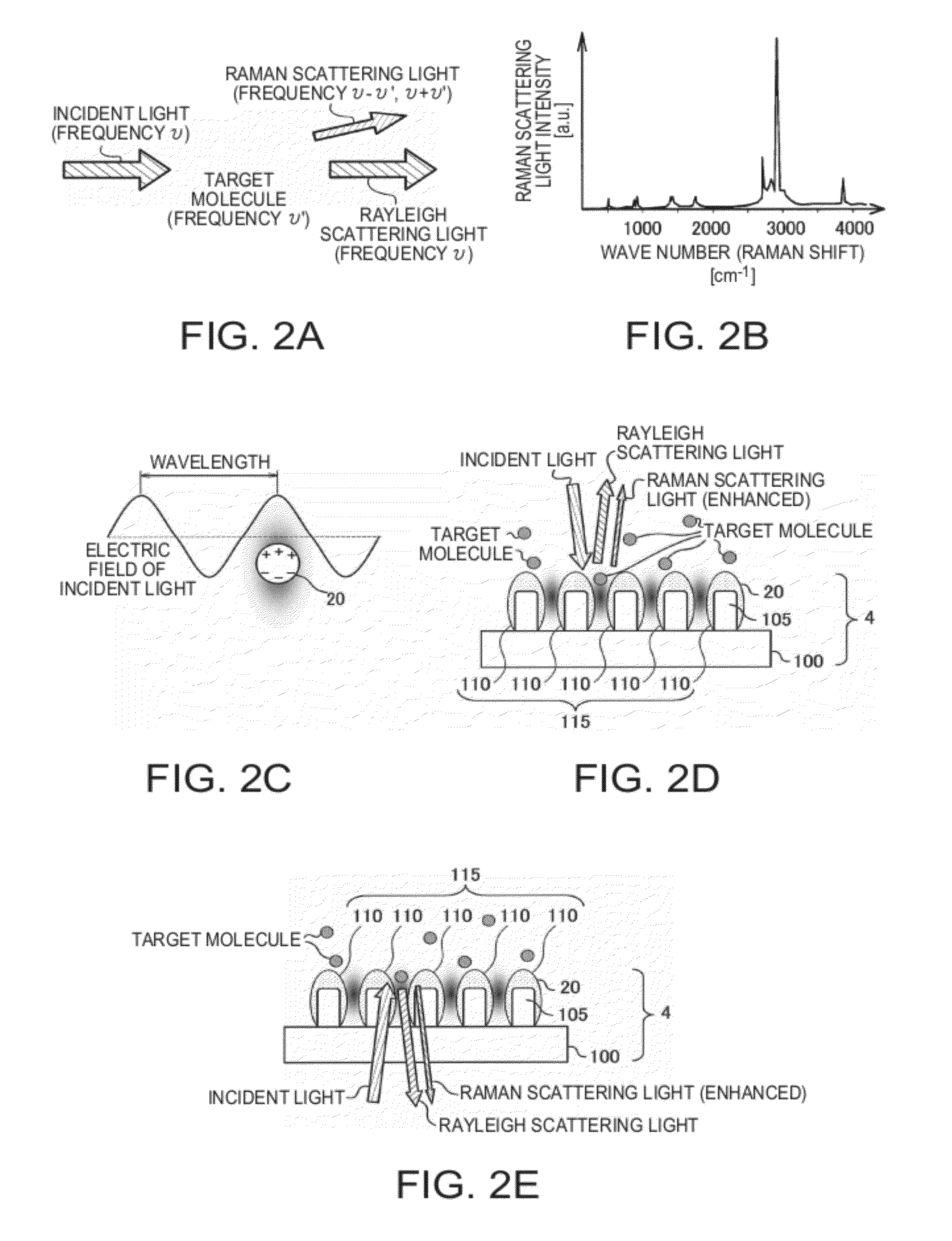
[0060]FIGS. 1A to 1D illustrate an exemplary configuration of a detection apparatus including an optical device unit according to an embodiment of the invention. As shown in FIG. 1A, the optical device unit includes an optical device 4 and a guide unit 420, and the detection apparatus includes the optical device unit, a light source A, an optical system, and a detection unit 5. The optical system (the first optical system) includes a half mirror 2 and a object lens 3. The light source A may radiate light having a predetermined polarization direction. In addition, the light source A may have a plurali...


PUM


Abstract

An optical device unit includes: an optical device that has an electrical conductor and that is capable of enhancing Raman scattering light generated by receiving light from a light source; and a guide unit that guides a gaseous sample to the optical device. The guide unit has a first fluid path for rotating the gaseous sample in an area facing the optical device.

Description

BACKGROUND[0001]1. Technical Field[0002]The present invention relates to an optical device unit and a detection apparatus.[0003]2. Related Art[0004]In general, a Raman spectroscopic apparatus includes a detector for obtaining Raman spectra by detecting Raman scattering light depending on a detection target substance. The detection target substance can be specified by performing a spectroscopic analysis using the Raman spectra. However, the signal intensity of the Raman scattering light is typically weak, and its detection sensitivity is low.[0005]JP-T-2008-529006 discloses a handheld Raman blood analyzer to provide surface-enhanced Raman scattering using gold colloid sol-gel / strips and increase the signal intensity of the Raman scattering light.[0006]In addition, a localized plasmon can be generated by irradiating excitation light onto a metal surface. The electric field can be locally enhanced by combining the excitation light and the localized plasmon. It is envisaged that Raman s...

Claims


Application Information

Patent Timeline
IPC IPC(8): G01J3/44G02F1/35
CPCG01N21/658
Inventor SAKAGAMI, YUSUKEAMAKO, JUN
Owner SEIKO EPSON CORP
Why Eureka
Try Eureka