Image forming apparatus and method for controlling fuser thereof

a technology of image forming apparatus and fuser, which is applied in the direction of electrographic process apparatus, instruments, optics, etc., can solve problems such as unstable paper feeding, and achieve the effect of minimizing offs

Active Publication Date: 2012-03-15
HEWLETT PACKARD DEV CO LP
View PDF1 Cites 10 Cited by
  • Summary
  • Abstract
  • Description
  • Claims
  • Application Information

AI Technical Summary

Benefits of technology

[0012]An embodiment or embodiments have been provided to address the above-mentioned and other problems and disadvantages occurring in the conventional arrangement, and an aspect provides an image forming apparatus for minimizing offset by controlling a fuser in a different controlling method according to a time interval of a printing paper entering the fuser, and a fuser controlling method thereof.

Problems solved by technology

When the (+) voltage overapplied is accumulated at the heat roller, the (−) charged toner is attracted to the heat roller and the toner on the heat roller can stain the next printing paper, which causes an offset.
When the bias voltage is shut down when the printing paper does not pass through the fuser, it is difficult to apply the voltage to the heat roller or the pressure roller at the same time as the paper passes through in case where the interval of the printing papers is shortened to implement a rapid machine, the paper feeding is unstable.

Method used


Image

  • Image forming apparatus and method for controlling fuser thereof
  • Image forming apparatus and method for controlling fuser thereof
  • Image forming apparatus and method for controlling fuser thereof

Examples


Embodiment Construction

[0029]Reference will now be made in detail to the embodiments, examples of which are illustrated in the accompanying drawings, wherein like reference numerals refer to the like elements throughout. The embodiments are described below to explain the embodiment by referring to the figures.

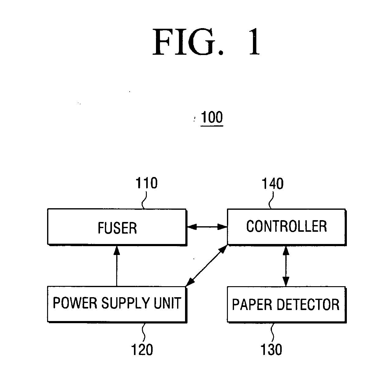
[0030]FIG. 1 is a block diagram of an image forming apparatus according to an exemplary embodiment of the invention.

[0031]Referring to FIG. 1, the image forming apparatus 100 may include a fuser 110, a power supply unit 120, a paper detector 130, and a controller 140.

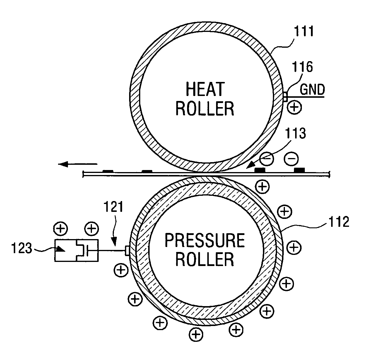
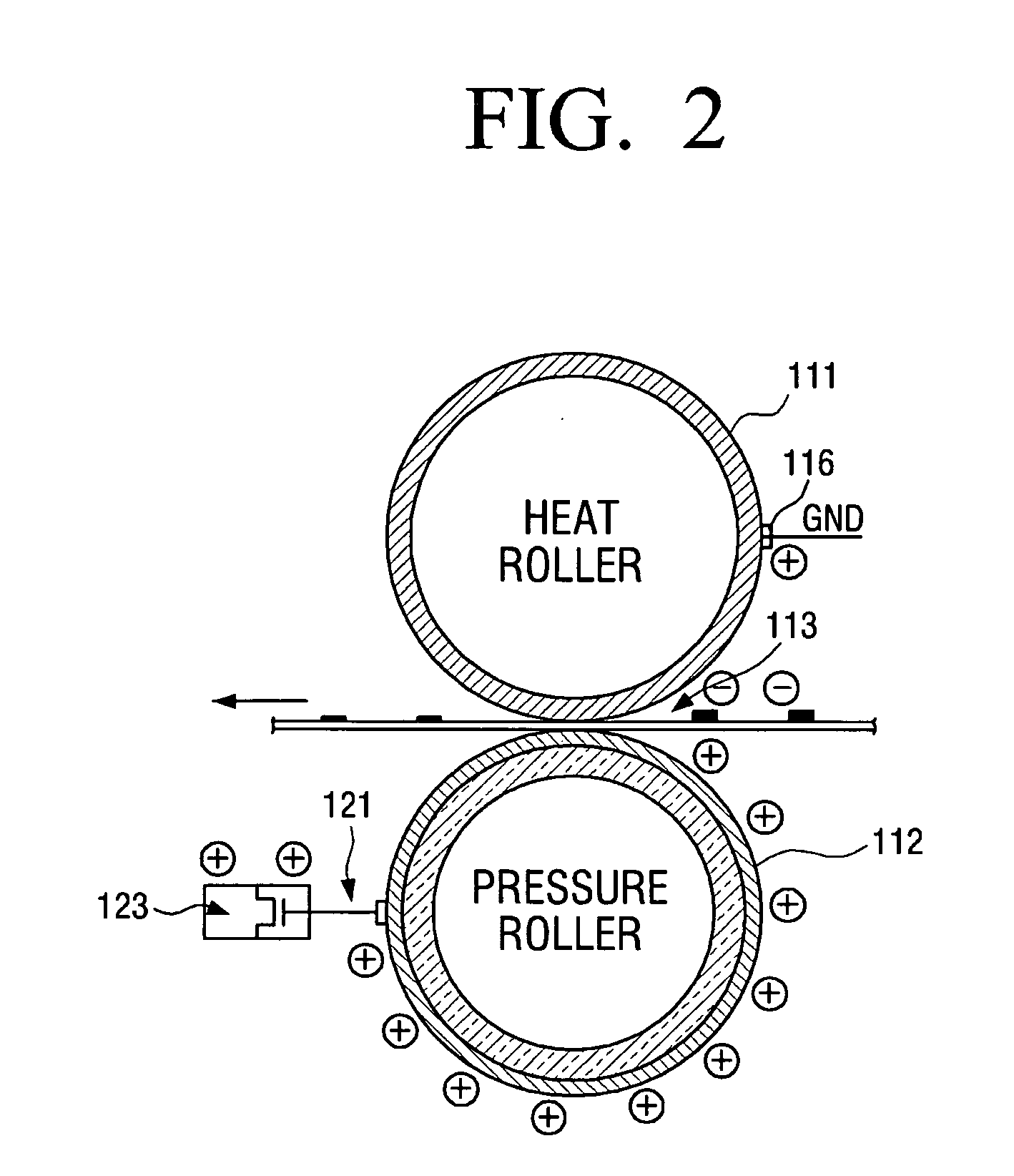
[0032]The fuser 110 fixes a charged toner onto a printing paper by applying heat and pressure over the printing paper. Structure and operations of the fuser 110 will be explained in detail by referring to FIG. 2.

[0033]The power supply unit 120 provides the fuser 110 with a bias voltage for fusing the charged toner on the printing paper. The power supply unit 120 may include a conductive member 121 and a switching unit 123.

[0034]The condu...


PUM


Abstract

An image forming apparatus includes a heat roller heated to a preset temperature; a pressure roller for having conductivity and forming a nip by pressure-contacting with the heat roller; a power supply unit to apply a bias voltage to the pressure roller; and a controller to, when a printing paper enters the nip, control the power supply unit to apply the bias voltage to the pressure roller. When a time interval is longer than a preset time, the controller can control the power supply unit not to apply the bias voltage when the printing paper is not placed in the nip, and when the time interval is shorter than the preset time, the controller can control the power supply unit to apply the bias voltage when the printing paper is not placed in the nip.

Description

CROSS-REFERENCE TO RELATED APPLICATIONS[0001]This application claims the priority benefit under 35 U.S.C. §119 (a) from Korean Patent Application No. 10-2010-0088895 filed on Sep. 10, 2010 in the Korean Intellectual Property Office, the entire disclosure of which is incorporated herein by reference.BACKGROUND[0002]1. Field[0003]Embodiments relate generally to an image forming apparatus and a fuser controlling method thereof. More particularly, the present disclosure relates to an image forming apparatus for minimizing offset by controlling a fuser in a different controlling method according to a time interval of a printing paper entering the fuser, and a fuser controlling method thereof.[0004]2. Description of the Related Art[0005]An image forming apparatus is a device which prints printing data generated at a printing control terminal such as computer, onto a printing paper. Examples of the image forming apparatus include a copier, a printer, a fax machine, and a Multi Function Per...

Claims


Application Information

Patent Timeline
Patent Type & Authority Applications(United States)
IPC IPC(8): G03G15/20
CPCG03G15/2025G03G15/2039G03G15/5004G03G15/2064
Inventor LEE, JIN-SEOKLEE, BONG-HEEJEON, SANG-UKKIM, DONG-KYUN
Owner HEWLETT PACKARD DEV CO LP
Why Eureka
Try Eureka