Steering mechanism for bi-directional catheter

a steering mechanism and catheter technology, applied in the field of catheters, can solve the problems of increasing the longitudinal movement reducing the efficiency of the steering lever, and adding to the friction loss in the operation of the steering assembly, so as to maximize the travel distance of the puller wire. , the effect of minimizing the offset angl

Active Publication Date: 2009-07-16
BIOSENSE WEBSTER INC
View PDF25 Cites 10 Cited by
  • Summary
  • Abstract
  • Description
  • Claims
  • Application Information

AI Technical Summary

Benefits of technology

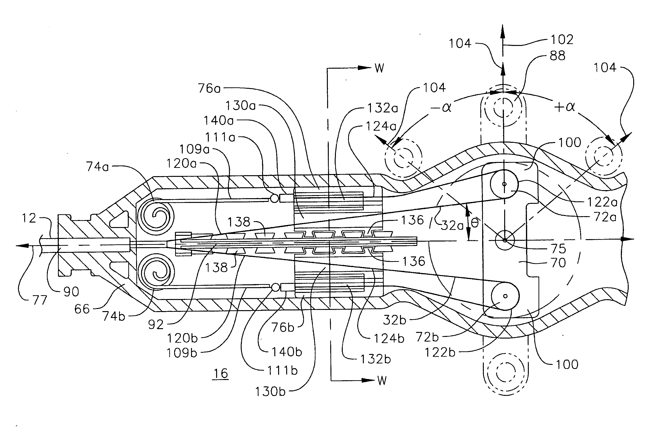
[0009]The present invention provides a bi-directional catheter with nearly double the throw in its catheter tip deflection. In particular, the travel path of each the puller wire includes a U-turn or doubling-back around a pulley which minimizes the offset angle between the puller wire and the longitudinal axis of the control handle while maximizing the travel distance of that puller wire for any given distance traveled by the pulley drawing the puller wire.

Problems solved by technology

The steering assembly of aforementioned U.S. Pat. No. 5,891,088 employs a configuration whereby the puller wires extend to the cam surfaces of the rotatable cam at a greater than generally desirable angle from the longitudinal axis of the catheter shaft, which decreases the efficiency of the steering lever and adds to friction losses in the operation of the steering assembly.
In addition, the steering assembly therein generally limits the amount of longitudinal movement of the puller wires for deflecting the catheter tip to only the circumference of the rotatable cam.

Method used


Image

  • Steering mechanism for bi-directional catheter
  • Steering mechanism for bi-directional catheter
  • Steering mechanism for bi-directional catheter

Examples


Embodiment Construction

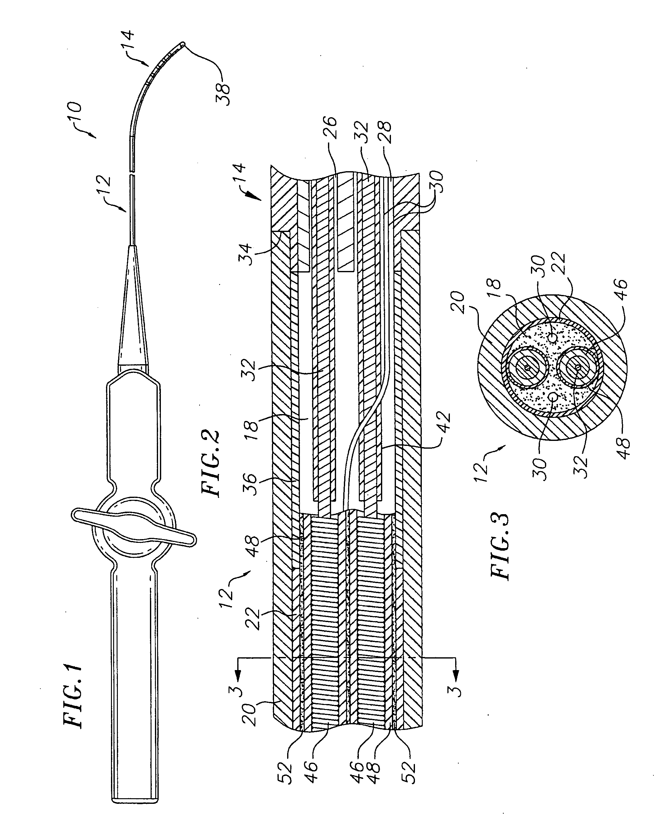
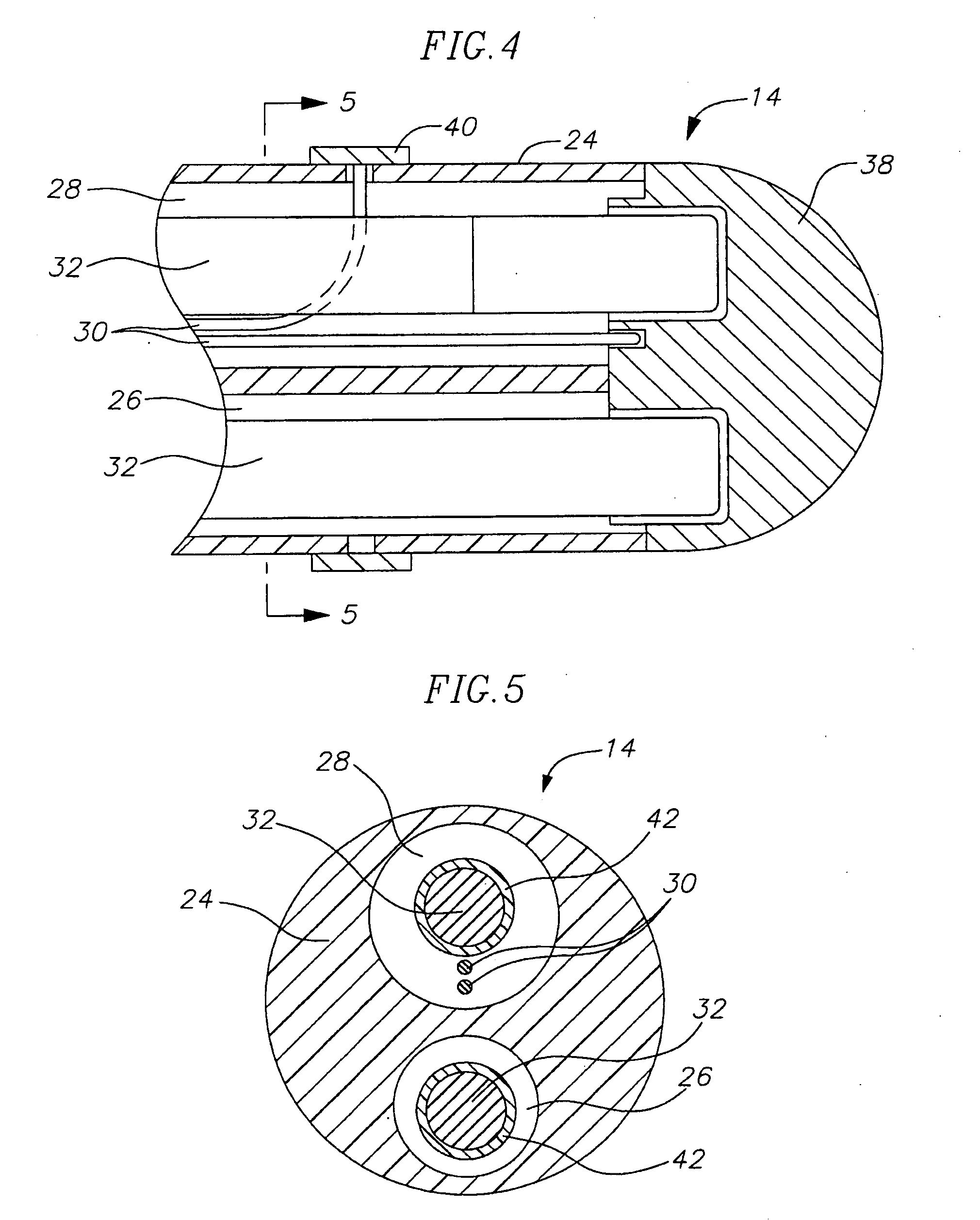
[0031]In an embodiment of the invention, there is provided a steerable bidirectional electrode catheter. As shown in FIG. 1, the catheter 10 comprises an elongated catheter body 12 having proximal and distal ends, a tip section 14 at the distal end of the catheter body 12, and a control handle 16 at the proximal end of the catheter body 12.

[0032]As shown in FIGS. 2 and 3, the catheter body 12 comprises an elongated tubular construction having a single axial or central lumen 18. The catheter body 12 is flexible, i.e., bendable, but substantially non-compressible along its length. The catheter body 12 can be of any suitable construction and made of any suitable material. A presently preferred construction comprises an outer wall 20 made of polyurethane or PEBAX. The outer wall 20 preferably comprises an imbedded braided mesh of stainless steel or the like to increase torsional stiffness of the catheter body 12 so that when the control handle 16 is rotated the tip section 14 will rotat...


PUM


Abstract

A bi-directional catheter with nearly double the throw in its catheter tip deflection defines a puller wire travel path having a U-turn a pulley which minimizes the offset angle between the puller wire and the longitudinal axis of the control handle while maximizing the travel distance of that puller wire for any given distance traveled by the pulley drawing the puller wire. In particular, the control handle of the catheter which includes a steering assembly having a lever arm carrying a pair of pulleys for drawing corresponding puller wires to deflect the tip section of the catheter. The pulleys are rotatably mounted on opposing portions of the lever arm such that one pulley is moved distally as the other pulley is moved proximally when the lever arm is rotated. Because each puller wire is trained on a respective pulley, rotation of the lever arm causes the pulley that is moved proximally to draw its puller wire to deflect the tip section in the direction of the off-axis lumen in which that puller wire extends.

Description

CROSS-REFERENCE TO RELATED APPLICATION(S)[0001]This application is a continuation of U.S. patent application Ser. No. 10 / 871,682 filed Jun. 14, 2004 and entitled STEERING MECHANISM FOR BI-DIRECTIONAL CATHETER, the entire content of which is incorporated herein by reference.FIELD OF INVENTION[0002]The present invention relates to improved bidirectional steerable catheters, and more particularly to catheters having bidirectional control handles.BACKGROUND OF INVENTION[0003]Electrode catheters have been in common use in medical practice for many years. They are used to stimulate and map electrical activity in the heart and to ablate sites of aberrant electrical activity. In use, the electrode catheter is inserted into a major vein or artery, e.g., femoral artery, and then guided into the chamber of the heart which is of concern. Within the heart, the ability to control the exact position and orientation of the catheter tip is critical and largely determines how useful the catheter is.[...

Claims


Application Information

Patent Timeline
Patent Type & Authority Applications(United States)
IPC IPC(8): A61M25/092A61M25/01
CPCA61M25/0147A61M25/0136A61M2025/015A61M2025/0166
Inventor SELKEE, THOMAS V.
Owner BIOSENSE WEBSTER INC
Why Eureka
Try Eureka