

Energy efficient ips blower assembly
- Summary
- Abstract
- Description
- Claims
- Application Information
AI Technical Summary
Problems solved by technology
Method used
Image

Examples
first embodiment
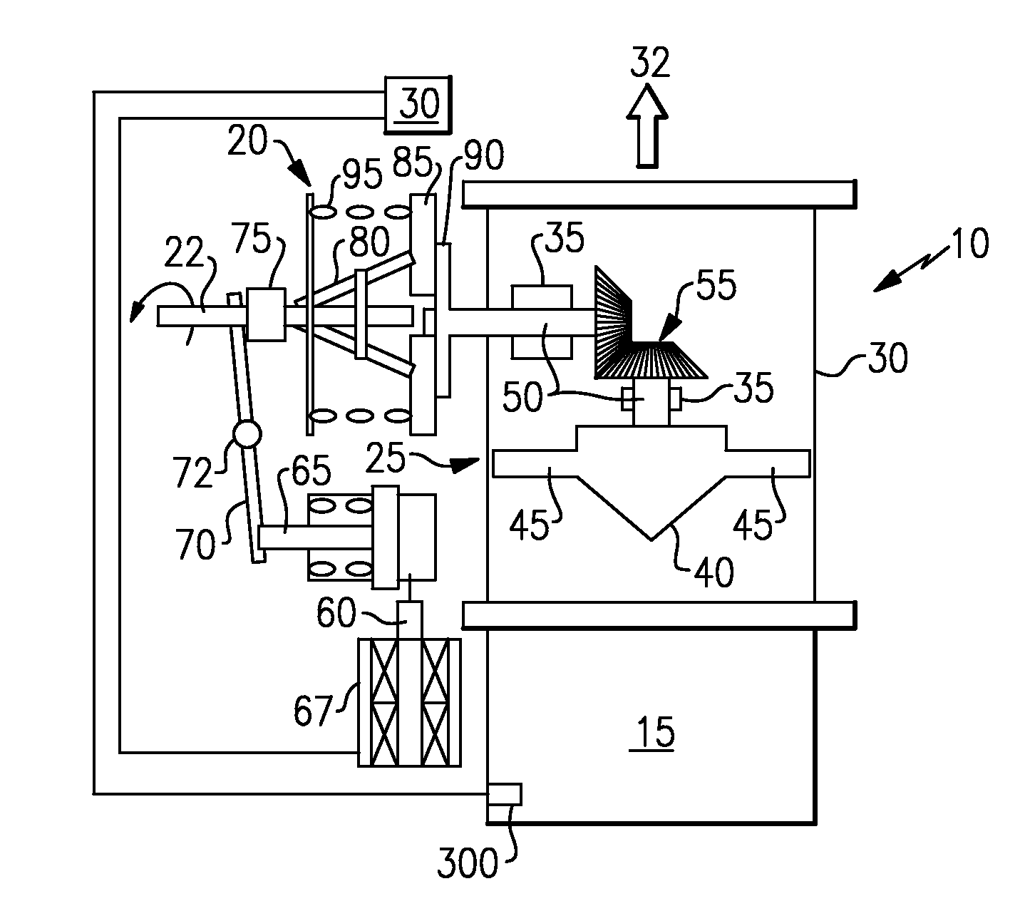
[0014]Referring now to FIG. 1, a clutch mechanism 20 is shown. The clutch mechanism, which is driven by an engine gear box (not shown) that rotates shaft 22, comprises; hydraulic fluid 60, which may be fuel or other liquid, a piston 65 driven by the fluid impelled by a pump (or a solenoid operated pressure signal) 67, a pivotable rod 70 pushed by the piston about pivot 72, a rotating throwout bearing 75 pushed by the rod 70, a plurality of rotating legs 80 pushed by the throwout bearing 75, a rotating clutch plate 85 pushed by the legs 80 and a fly-wheel 90 that engages the rotating clutch plate 85. The fly-wheel 90 is fixedly attached to impeller shaft 50, and contact with the rotating clutch plate thereby causes the fan blades 45 to turn due to the now rotating impeller shaft 50 and draw the not-so-clean air through the housing 30 to ambient 32.
[0015]Spring 95 acts to pull the legs 80 and clutch plate 85 away from the fly-wheel if hydraulic pressure is removed from the piston 65. ...
second embodiment
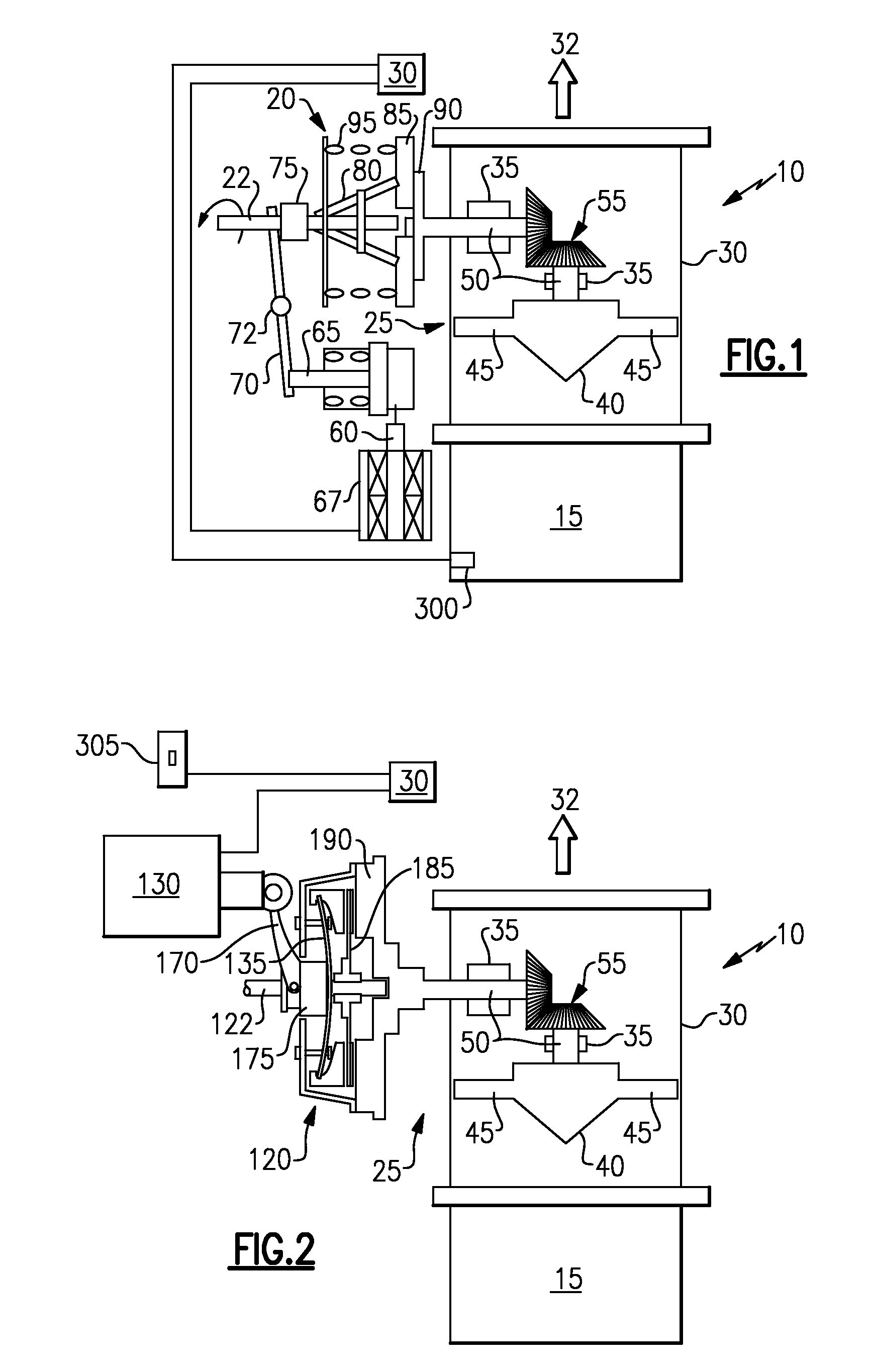
[0016]Referring now to FIG. 2, a clutch mechanism 120 is shown. The clutch mechanism 120 which is driven by an engine gear box (not shown) that rotates shaft 122, comprises; an electric ram 130, a pivot arm 170 driven by the electric ram, a rotating throwout bearing 175 pushed by the rod 170, a diaphragm spring 135 flexed by the throwout bearing, a rotating pressure plate 140 pushed by the diaphragm spring 135, and a rotating clutch plate 185 that is pushed by the pressure plate 140 into contact with a fly-wheel 190. The fly-wheel 190 is fixedly attached to impeller shaft 50 and contact with the rotating clutch plate 185 causes the fan blades 45 to turn due to the now rotating impeller shaft 50 and draw the not-so-clean air through the housing 30 to ambient 32.
[0017]Diaphragm spring 135 acts to pull the pressure plate 140 away from clutch plate 185 to disengage the clutch mechanism from the fly-wheel 190 if the electric ram does not urge the pivot arm 170 against throwout bearing 17...
third embodiment
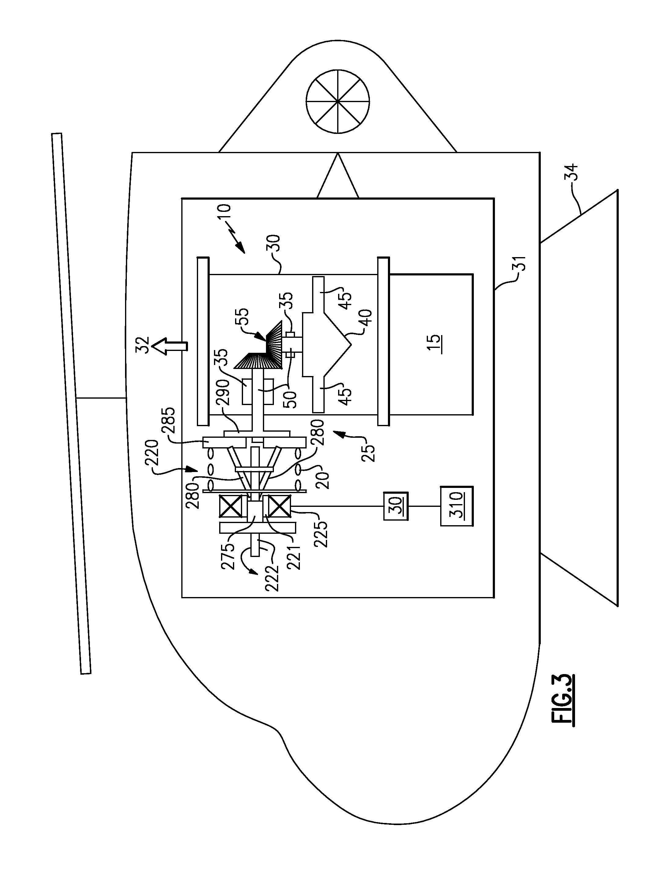
[0018]Referring now to FIG. 3, a clutch mechanism 220 is shown. The clutch mechanism, which is driven by an engine gear box (not shown) that rotates shaft 222, comprises; an electric motor 225, a throwout bearing 275 driven axially along ramp or ball race or the like 221 (shown schematically) by the electric motor, a plurality of rotating legs 280 pushed by the throwout bearing 275, a rotating clutch plate 285 pushed by the legs 280 and a fly-wheel 290 that engages the rotating clutch plate. The fly-wheel 290 is fixedly attached to impeller shaft 50, and contact with the rotating clutch plate 285 thereby causes the fan blades 45 to turn due to the now rotating impeller shaft 50 and draw the not-so-clean air through the housing 30 to ambient 32.
[0019]Spring 295 acts to pull the legs 280 and clutch plate 285 away from the fly-wheel 290 if the electric motor 225 is turned off. Controller 30 acts to actuate and deactuate electric motor 225.
[0020]Actuation of the electric motor 225, pump...
PUM
 Abstract
Description
Claims
Application Information