Semicondcutor device and method of producing the same
a technology of semiconductor substrate and cutting device, which is applied in the direction of semiconductor substrate, electrical apparatus, basic electric elements, etc., can solve the problems of inability to form nsup>+/sup> field stop layer in a position, difficulty in sufficiently activating impurities, etc., and achieve the effect of soft recovery characteristics and preventing the breakage of semiconductor substra
- Summary
- Abstract
- Description
- Claims
- Application Information
AI Technical Summary
Benefits of technology
Problems solved by technology
Method used
Image
Examples
embodiment 1
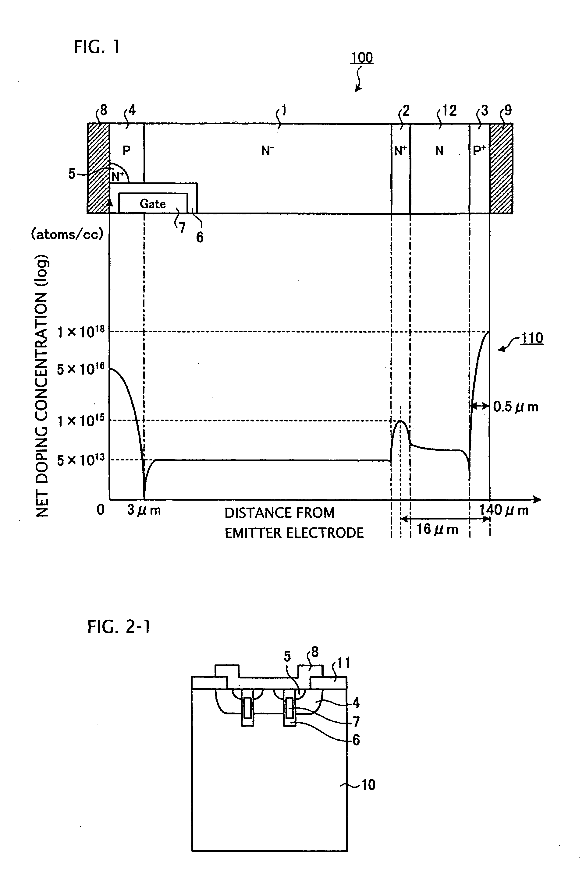
[0077]FIG. 1 is a view showing the configuration of a semiconductor device and the net doping concentration thereof. As shown in a section 100 of the semiconductor device in FIG. 1, for example, an N+ first buffer layer (N+ field stop layer) 2 as a second semiconductor layer, an N second buffer layer 12 as a third semiconductor layer and a P+ collector layer 3 as a fourth semiconductor layer are formed in this order on one principal surface (first principal surface) of an N− drift layer 1 as a first semiconductor layer. A P base layer 4 as a fifth semiconductor layer is formed on the other principal surface (second principal surface) of the N− drift layer 1. An N source layer 5 as a sixth semiconductor layer is formed in part of a surface layer of the P base layer 4 so as to be far from the N− drift layer 1. A gate electrode 7 is formed through a gate insulating film 6 in a trench which passes through the N source layer 5 and the P base layer 4 and reaches the N− drift layer 1. An ...
embodiment 2
[0139]It is hence to be understood that helium ions, lithium ions or oxygen ions are preferred as other elements to be injected than protons in accordance with As shown in FIG. 6 and FIGS. 11 to 13, it is found that the preferred acceleration voltage is 200 keV at minimum and 30 MeV at maximum and the preferred acceleration voltage for injection of protons is 2 MeV at maximum.
[0140]FIG. 14 is a view showing the configuration and net doping concentration of a semiconductor device according to Embodiment 3. As shown in a section 200 of the semiconductor device in FIG. 14, the semiconductor device according to Embodiment 3 includes, in addition to the semiconductor device of Embodiment 1 shown in FIG. 1, an N+ cathode buffer layer 22 (seventh semiconductor layer) provided between the N second buffer layer 12 and the P+ collector layer 3 and being higher in concentration than the N second buffer layer 12. The other configuration is the same as in Embodiment 1 and like numerals refer to...
embodiment 3
[0143], the depletion layer spread from the emitter side into the drift layer can be stopped more surely by the N+ cathode buffer layer 22 before the depletion layer reaches the P+ collector layer 3. Accordingly, the incomplete formation of the buffer layer can be prevented, so that the percentage of leakage current non-defective products can be improved more greatly.
[0144]FIG. 15 is a graph showing turn-off waveforms of the semiconductor device according to Embodiments 1 to 3 and the semiconductor device including the field stop layer according to the related art. In FIG. 15, the thick solid line expresses the collector current IC and collector-emitter voltage VC of the semiconductor device according to Embodiments 1 to 3. The thin broken line expresses the collector current IC and collector-emitter voltage VC of the semiconductor device including the field stop layer according to the related art (see FIG. 19).
[0145]All the turn-off waveforms shown in FIG. 15 are waveforms in a snu...
PUM
 Abstract
Description
Claims
Application Information
 - R&D
- Intellectual Property
- Life Sciences
- Materials
- Tech Scout
- Unparalleled Data Quality
- Higher Quality Content
- 60% Fewer Hallucinations
Browse by: Latest US Patents, China's latest patents, Technical Efficacy Thesaurus, Application Domain, Technology Topic, Popular Technical Reports.
© 2025 PatSnap. All rights reserved.Legal|Privacy policy|Modern Slavery Act Transparency Statement|Sitemap|About US| Contact US: help@patsnap.com


