Synchronous network of superspeed and non-superspeed USB devices

a network and super-fast technology, applied in the direction of instruments, data conversion, generating/distributing signals, etc., can solve the problems of usb 2.0 specification lacked a mechanism for synchronising devices to any great precision, inter-device synchronization is not addressed, usb 2 lacks a synchronization mechanism

Inactive Publication Date: 2012-03-15
CHRONOLOGIC PTY LTD
View PDF40 Cites 41 Cited by
  • Summary
  • Abstract
  • Description
  • Claims
  • Application Information

AI Technical Summary

Benefits of technology

[0057]Isochronous transfers can be specified to begin in a particular USB Frame (or microframe). It will be apparent to those skilled in the art that the method of this aspect described above may include determining the transmission time (timestamp) of a plurality of Isochronous Timestamp Packets to each of the plurality of SuperSpeed USB devices, in the time domain of the non-SuperSpeed synchronisation channels, thereby providing more information as to the mapping between time domains. Furthermore statistical means may be employed to improve the accuracy of the mapping.
[0080]In another embodiment, the method includes generating the synchronisation information by circuitry at the USB Hub. The synchronisation information may be received by circuitry at the USB Hub from an external source, such as a Global Positioning System (GPS) referenced clock source, an atomic clock, an Ethernet (in the form of, for example, Network Time Protocol (NTP) or IEEE-1588 Precision Time Protocol (PTP)), a wireless synchronisation mechanism, a CompactPCI instrumentation system, a PXI instrumentation system, a VXI instrumentation system or another instrumentation system. In this way, the synchronisation channel is capable of providing a precision timing reference across a widely distributed network, accurate to an external reference clock.
[0122]Furthermore, the temporal adjustment is valid for compensating the cable-propagation-time for all of the synchronisation information. Therefore providing a generic phase adjustment for all of the synchronisation information allows synchronisation of clocking signals, absolute time reference signals, trigger signals and any other form of synchronisation information for each of the USB devices.

Problems solved by technology

However, USB was user focussed so the USB 2.0 specification lacked a mechanism for synchronising devices to any great precision.
This provides a degree of synchronization sufficient to read smart card information into a host PC but, as this approach is directed to a smart card reader, inter-device synchronization is not addressed.
All of the above systems work within the bounds of conventional USB 2.0 and as such are limited in several areas.
USB 2.0 is limited in range by the device response timeout.
In particular, the background art synchronisation schemes discussed above will not work with the new 5 Gb / s protocol (termed ‘SuperSpeed USB’) because it does away with the broadcast mechanism for SOF packets.
Very high speed communication systems consume large amounts of power owing to high bit rates.
This significantly affects any extension of the synchronisation schemes of, for example, U.S. patent application Ser. No. 12 / 279,328, whose method and apparatus for synchronising devices is based on a broadcast clock carrier signal that is delivered to each device on the bus, which is unsuitable in SuperSpeed USB.
A heavily burdened Hub function can therefore add significant non-deterministic delays in packet transmission through the system.
Unfortunately the Isochronous Timestamp packet can be delayed in propagation down the USB network.
USB 3.0 also does not provide a way of determining the propagation time of packets in SuperSpeed USB and hence no way of accurately knowing the phase relationship between time domains on different USB devices.
Phase differences of several hundred nanoseconds are expected to be a best case scenario with SuperSpeed USB making it impractical for instrumentation or other precision timing requirements.
This continual messaging consumes bandwidth and limits the accuracy of the possible synchronisation to several hundred nano-seconds in a point-to-point arrangement and substantially lower accuracy (typically micro-seconds) in a conventional switched subnet.

Method used


Image

  • Synchronous network of superspeed and non-superspeed USB devices
  • Synchronous network of superspeed and non-superspeed USB devices
  • Synchronous network of superspeed and non-superspeed USB devices

Examples


Embodiment Construction

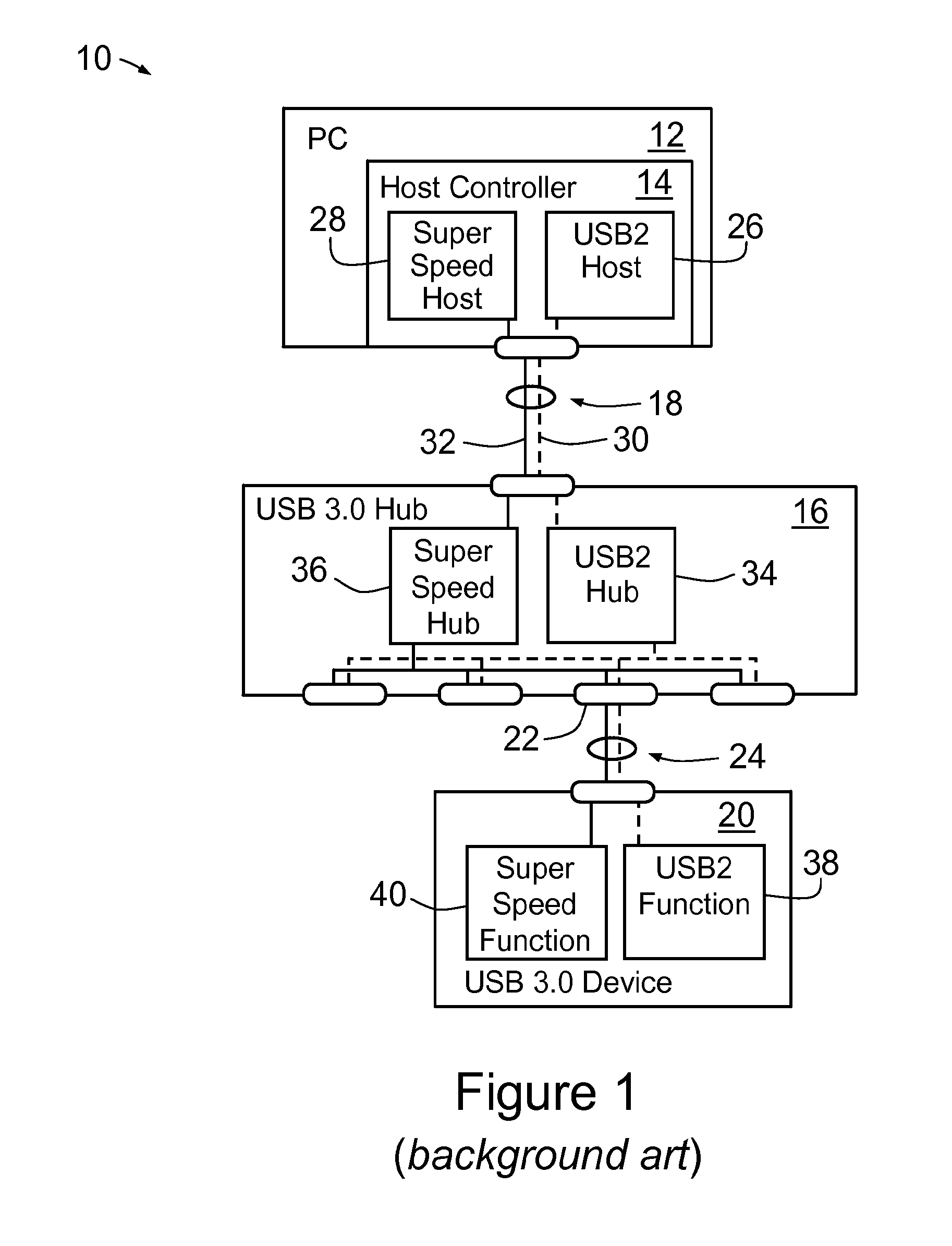
[0207]A synchronised USB according to a first embodiment of the present invention is shown schematically at 70 in FIG. 2, provided in a personal computer (PC) 72. PC 72 includes a SuperSpeed USB Host Controller 74 that is connected to a network 76 containing a SuperSpeed USB Timing Hub 78, a SuperSpeed USB device 80 and a non-SuperSpeed USB device 82. USB Host Controller 74 is connected to USB Timing Hub 78 by compound USB cable 84 comprising SuperSpeed conductors 86 and non-SuperSpeed conductors 88.

[0208]USB Timing Hub 78 supports attachment of both a SuperSpeed USB device 80 and non-SuperSpeed USB device 82, so both SuperSpeed conductors 86 and non-SuperSpeed conductors 88 carry signals between SuperSpeed USB Host Controller 74 and USB Timing Hub 78.

[0209]SuperSpeed USB device 80 is connected to USB Timing Hub 78 by SuperSpeed-compliant compound USB cable 90, comprising SuperSpeed conductors 92 and non-SuperSpeed conductors 94. As device USB 80 is a SuperSpeed USB device, USB Timi...


PUM


Abstract

A method of synchronising the operation of a plurality of SuperSpeed USB devices and a plurality of non-SuperSpeed USB devices is provided. The method includes establishing a SuperSpeed synchronisation channel for each of the plurality of SuperSpeed USB devices; establishing a non-SuperSpeed synchronisation channel for each of the plurality of non-SuperSpeed USB devices; synchronising a respective local clock of each of the plurality of SuperSpeed USB devices; synchronising a respective local clock of each of the plurality of non-SuperSpeed USB devices; and synchronising the SuperSpeed and non-SuperSpeed synchronisation channels so that the SuperSpeed and non-SuperSpeed devices can operate in synchrony.

Description

FIELD OF THE INVENTION[0001]The present invention relates to a method and apparatus for providing a synchronization and timing system, with connectivity based on revision three of the Universal Serial Bus (USB) architecture (or USB 3.0), of particular but by no means exclusive use in providing clocks, data acquisition and automation and control of test and measurement equipment, instrumentation interfaces and process control equipment, synchronized to an essentially arbitrary degree in either a local environment or in a distributed scheme.BACKGROUND OF THE INVENTION[0002]The USB specification up to and including revision 2.0 was intended to facilitate the interoperation of devices from different vendors in an open architecture. High Speed USB data is encoded using differential signalling (viz. in which two wires transfer the information) in the form of the difference between the signal levels of those two wires. The USB 2.0 specification is intended as an enhancement to the PC archi...

Claims


Application Information

Patent Timeline
Patent Type & Authority Applications(United States)
IPC IPC(8): G06F3/00
CPCG06F1/12G06F13/4022G06F2213/0042H04L7/04G06F13/4027H04L7/08G06F1/08G06F13/10G06F13/423G06F13/4282G06F11/3027G06F13/405
Inventor FOSTER, PETER GRAHAM
Owner CHRONOLOGIC PTY LTD
Why Eureka
Try Eureka