

Pin extraction tool
Patent Information
- Authority / Receiving Office
- US · United States
- Current Assignee / Owner
- Publication Date
- 2012-03-22
Smart Images
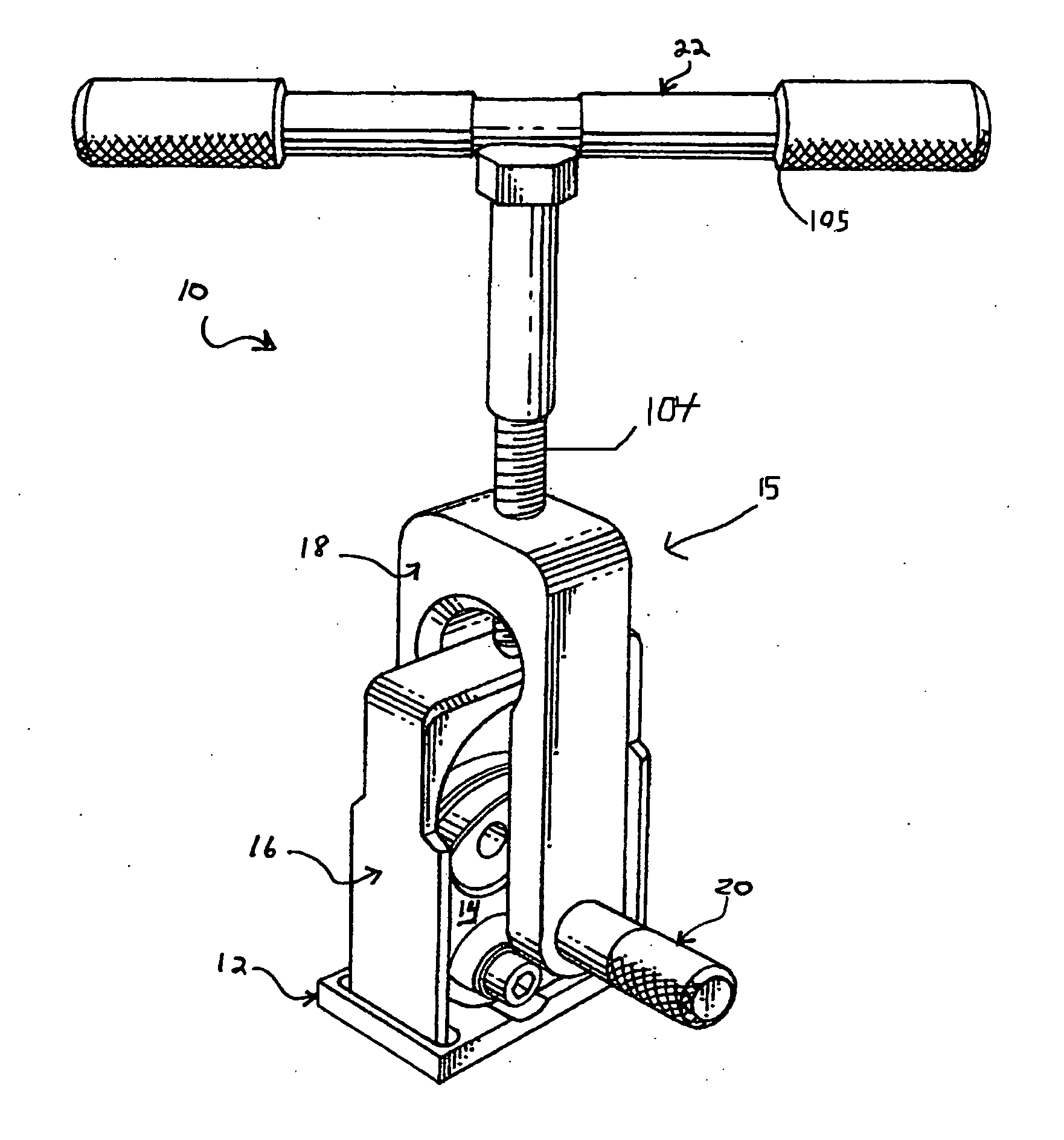
Figure 1 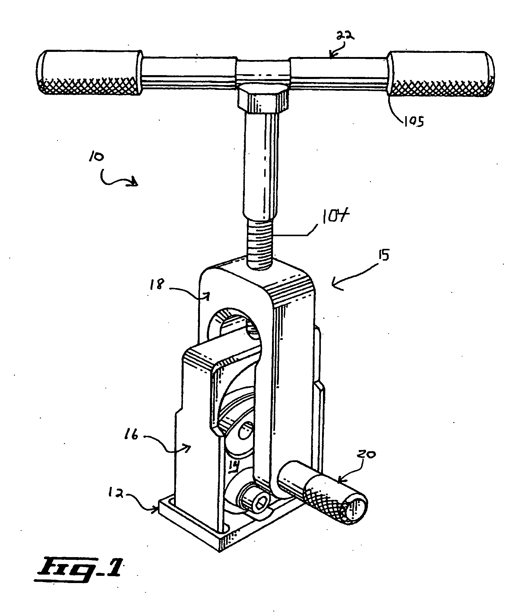
Figure 2 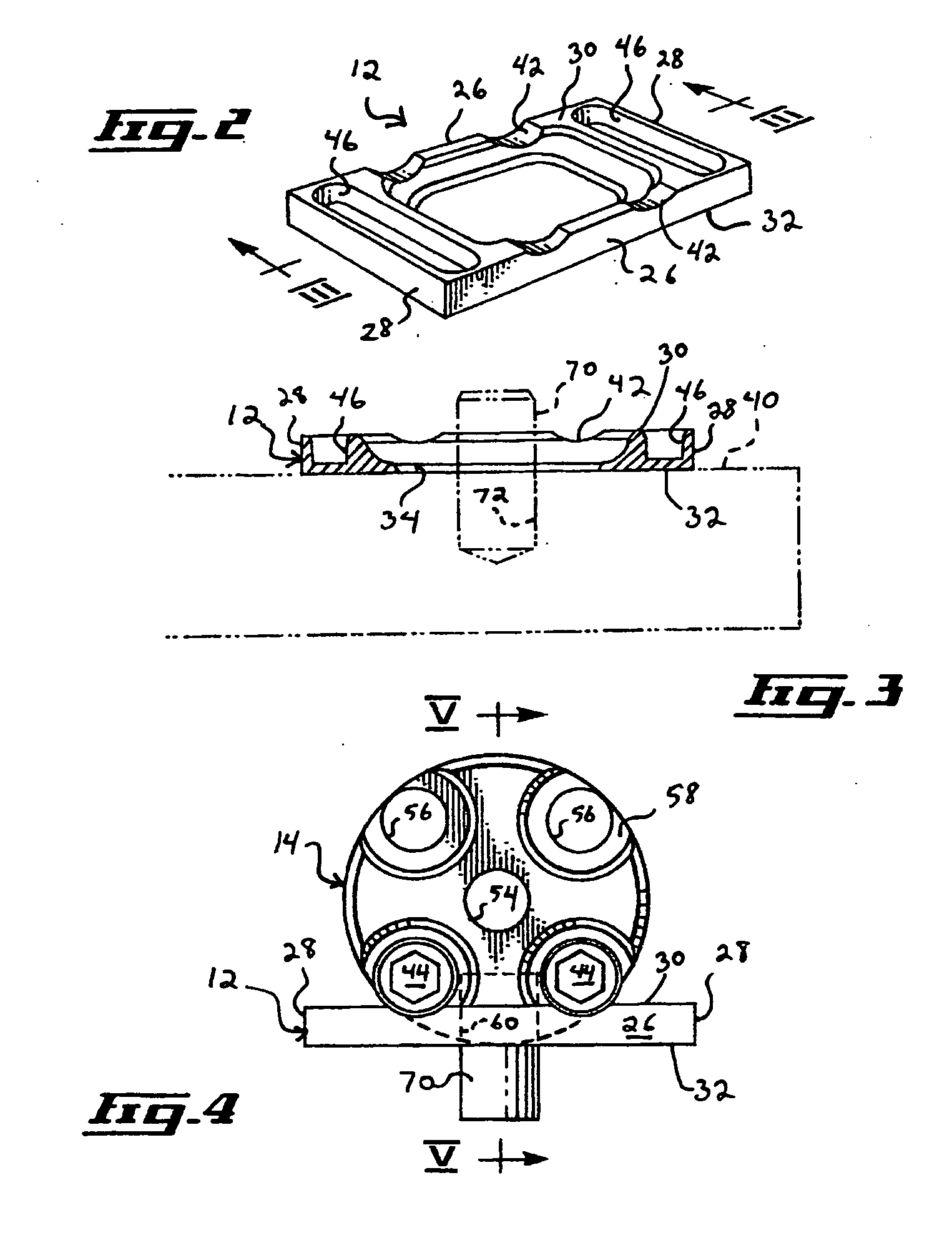
Figure 3
Abstract
Description
[0001] The present application claims priority from UK Request Application Serial Number 1015444.1 filed on Sep. 16, 2010, the contents of which is hereby incorporated by reference in its entirety.FIELD OF THE INVENTION
[0002] The present invention relates generally to mechanical extraction tools and, more particularly, to an extraction tool used for extracting headless pins, such as dowel pins, press mounted in blind holes provided through the mounting surface of tooling plates, injection mold elements, and the likes.BACKGROUND
[0003] Dowel pin extraction tools are known in the art and are useful for extracting headless pins that are press mounted in blind holes provided through the mounting surface of tooling plates on drilling machines, milling machines, Computed Numerical Control (or CNC) machine tools, multi-part injection molds, and the likes.
[0004] Some examples of the prior art are U.S. Pat. Application No. US2003 / 0140473, to Martantette (published in July 2003), U.S. Pat. No. 5,6...
Examples
Embodiment Construction
[0040]Referring to FIG. 1, there is shown various aspects of a tool 10 according to an embodiment the present invention. The tool 10 is usable for extracting a pin 70 (shown for example in FIG. 3) inserted in a component bore 72 (shown also for example in FIG. 3), the component bore 72 extending into a pin receiving component 40 (shown also for example in FIG. 3). For example, the pin 70 is a headless pin presenting a substantially smooth surface, such as a dowel pin, press mounted in a component bore 72 taking the form of a blind hole provided through the mounting surface of a pin receiving component 40 in the form of a tooling plate or an injection mold element. However, the tool 10 is usable for other types of pins 70 without detracting from the present invention.
[0041]Referring to FIG. 1, the tool 10 includes a base element 12, a pin gripping element 14, and a gripping element mount 15. The gripping element mount 15 mounts the pin gripping element 14 to the base element 12. In s...