Conveying device and deposition device using same
a technology of conveying device and deposition device, which is applied in the direction of transportation and packaging, locomotives, locomotive transmissions, etc., can solve the problem of difficult uniform thickness of films formed on different surfaces of electronic devices
- Summary
- Abstract
- Description
- Claims
- Application Information
AI Technical Summary
Problems solved by technology
Method used
Image

Examples
first embodiment
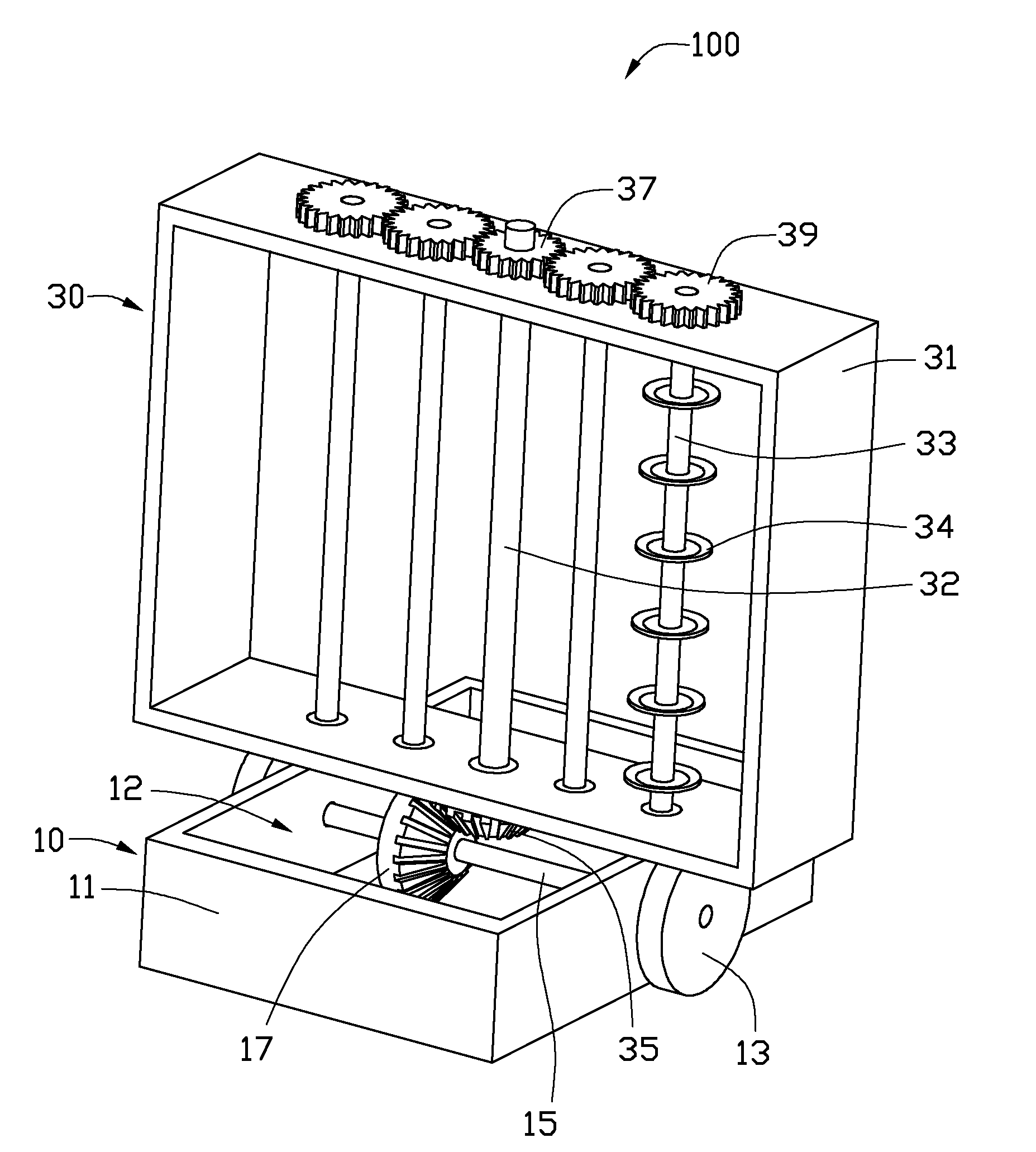
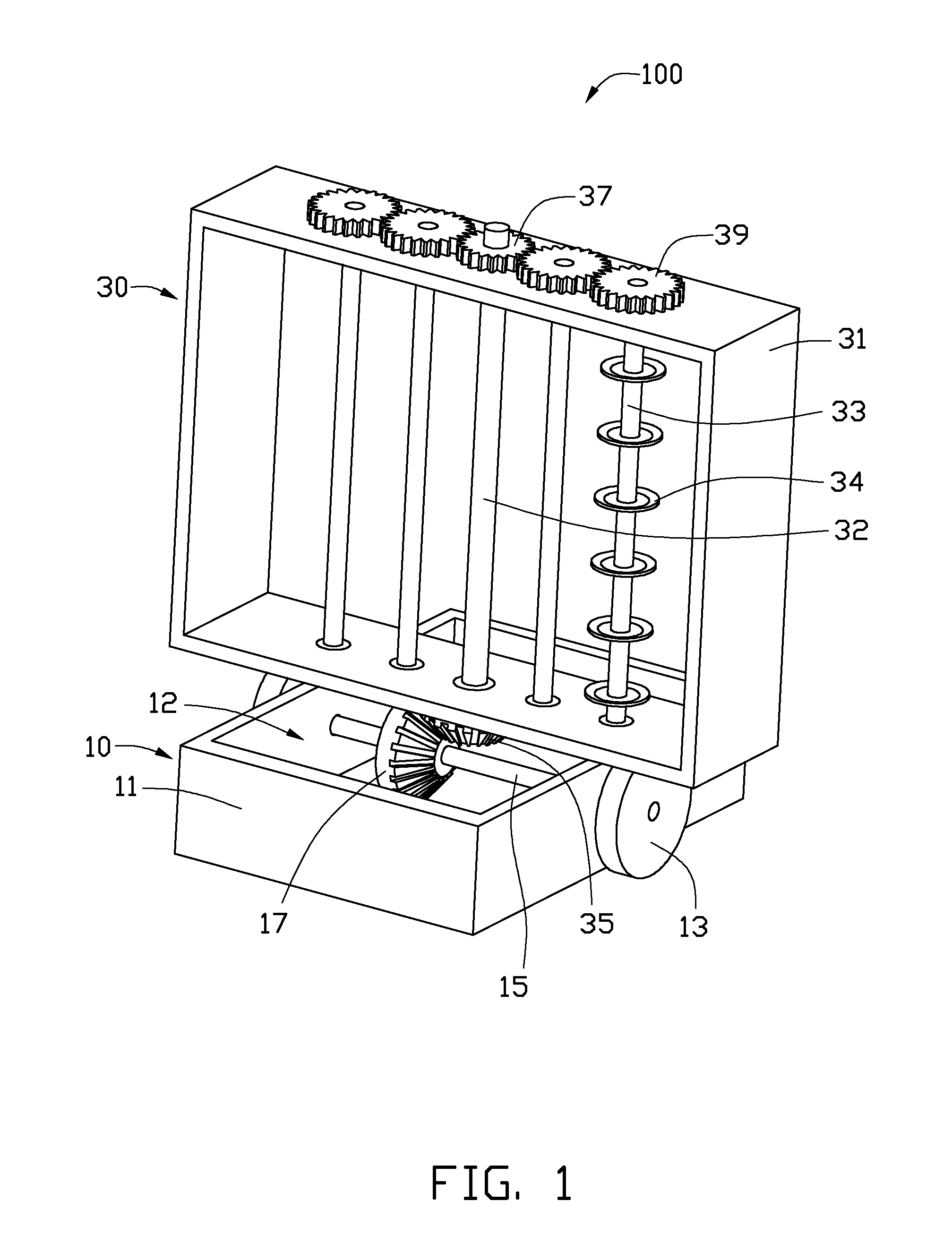
[0013]Referring to FIGS. 1-3, a conveying device 100 for a deposition device in accordance with the disclosure includes a transport device 10 and a carrier 30. The carrier 30 is mounted on the transport device 10. The carrier 30 is configured for supporting a number of workpieces.
[0014]The transport device 10 includes a main body 11, two wheels 13, a connection shaft 15 and a first bevel gear 17.
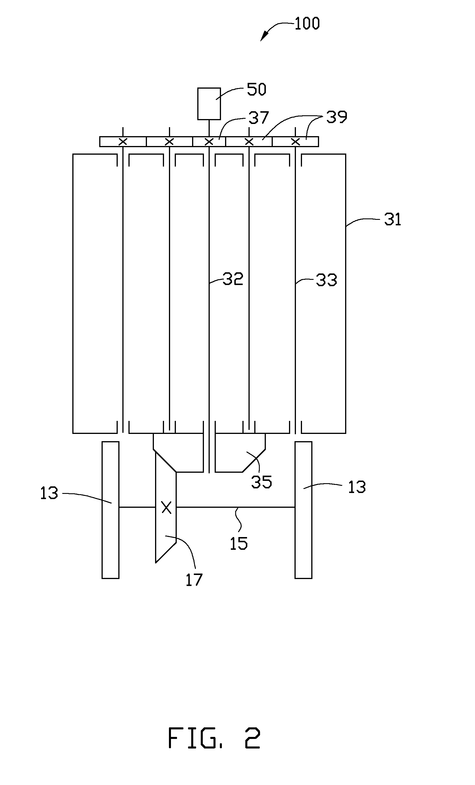
[0015]The main body 11 is a substantially hollow cuboid and defines a cavity 12. The connection shaft 15 passes through two opposite sidewalls of the main body 11. The two wheels 13 are respectively positioned on two ends of the connection shaft 15. The first bevel gear 17 is sleeved on the connection shaft 15 and is received in the cavity 12 of the main body 11. The main body 11 is movable according to the at least two wheels 13 and the connection shaft 15.
[0016]The carrier 30 includes a revolving frame 31, a number of carrying bars 33, a second bevel gear 35, a rotating shaft 32, a drive g...
second embodiment
[0020]Referring to FIG. 4, a conveying device 200 in accordance with the disclosure is similar to the conveying device 100 of FIGS. 1 to 3, except that a third bevel gear 19 is sleeved on the connection shaft 15 and a fourth bevel gear 36 is sleeved on the rotating shaft 32. The third bevel gear 19 is located between the two wheels 13 and is close to the first bevel gear 17. The fourth bevel gear 36 is meshed with the third bevel gear 19.
[0021]When the conveying device 200 is moving, the first bevel gear 17 drives the second bevel gear 35 to rotates. The revolving frame 31 rotates relative to the rotating shaft 32 and each of the four carrying bars 33 rotates relative to the axis thereof under the driving of the second bevel gear 35. A diameter of the third bevel gear 19 is smaller than that of the first bevel gear 17, and a diameter of the fourth bevel 36 is smaller than that of the second bevel gear 35. The rotation velocity of each carrying bar 33 can be finely adjusted by select...
PUM
| Property | Measurement | Unit |
|---|---|---|
| diameter | aaaaa | aaaaa |
| thicknesses | aaaaa | aaaaa |
| angle | aaaaa | aaaaa |
Abstract
Description
Claims
Application Information
 - R&D
- Intellectual Property
- Life Sciences
- Materials
- Tech Scout
- Unparalleled Data Quality
- Higher Quality Content
- 60% Fewer Hallucinations
Browse by: Latest US Patents, China's latest patents, Technical Efficacy Thesaurus, Application Domain, Technology Topic, Popular Technical Reports.
© 2025 PatSnap. All rights reserved.Legal|Privacy policy|Modern Slavery Act Transparency Statement|Sitemap|About US| Contact US: help@patsnap.com