
Pneumatic tire

a pneumatic tire and tire body technology, applied in vehicle components, non-skid devices, rolling resistance optimization, etc., can solve the problems of deteriorating steering stability, achieve effective steering stability, suppress the effect of rigidity reduction, and reduce rolling resistan

Active Publication Date: 2012-03-22
TOYO TIRE & RUBBER CO LTD
View PDF5 Cites 9 Cited by
  • Summary
  • Abstract
  • Description
  • Claims
  • Application Information

AI Technical Summary

Benefits of technology

[0007]The present invention has been made in view of the above circumstances, and an object thereof is to provide a pneumatic tire which can reduce a rolling resistance while maintaining steering stability.
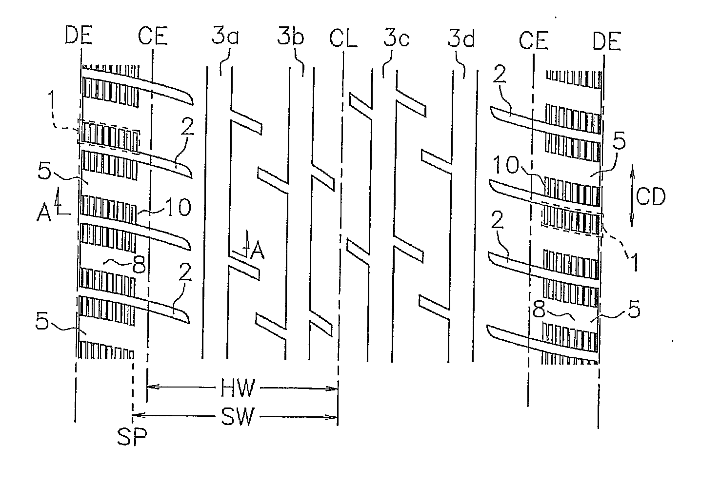
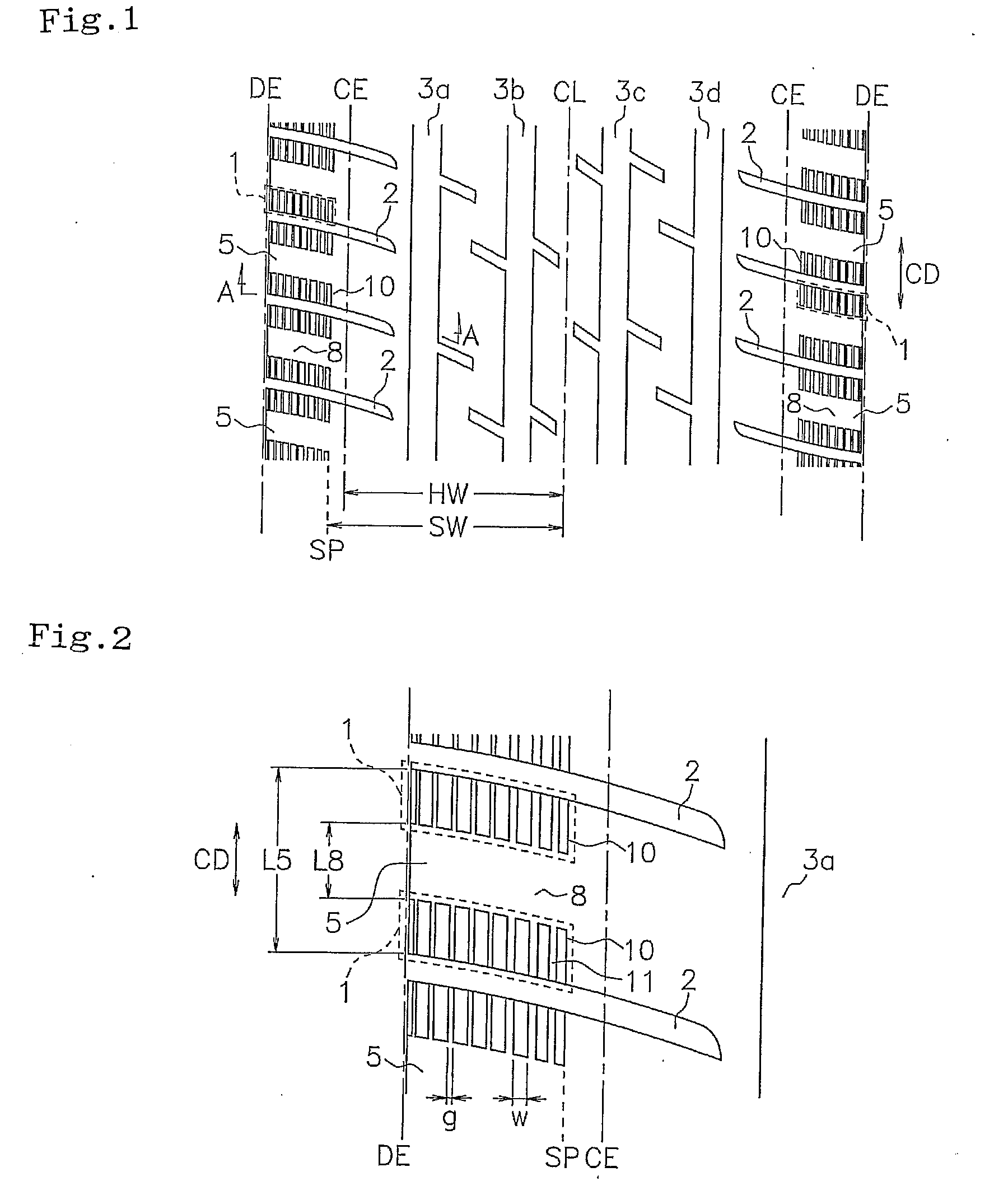
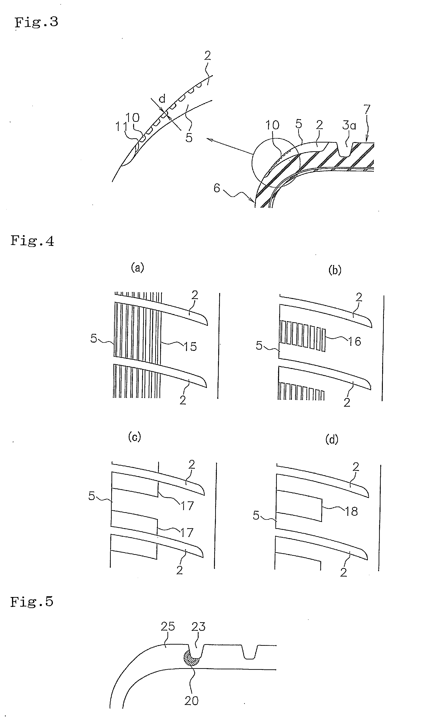
[0009]In the pneumatic tire according to the present invention, since the depression region in which a plurality of depressions extending in the tire circumferential direction are arranged in the tire width direction is formed in the surface of the shoulder block, a buttress portion of the tire deflects easily, and it is possible to reduce the rolling resistance by dispersing the strain which tends to concentrate on the periphery of the groove bottom of the main groove facing the shoulder block. In addition, since the depression region is formed in the outer side in the tire width direction than the ground-contact end, and the depressions are segmented in the center portion in the tire circumferential direction of the shoulder block, it is possible to effectively maintain the steering stability by suppressing the rigidity reduction caused by the depression region. Further, since the depressions are open to the lateral groove, the rigidity change in the tire circumferential direction becomes gentle, and it is possible to enhance the effect of reducing the rolling resistance by making the strain generated in the periphery of the groove bottom of the lateral groove comparting the shoulder block small.
[0010]In the present invention, it is preferable that the depression region extends from a start end position in the outer side in the tire width direction than the ground-contact end to the vicinity of an end edge position of the shoulder block close to a side wall portion. According to the structure mentioned above, the steering stability is easily maintained by preferably suppressing the rigidity reduction caused by forming the depression region. Particularly, since it is possible to prevent an extreme reduction of the ground-contact area at a cornering time of the limit area when the ground-contact surface of the tire is expanded to the outer side in the tire width direction, the steering stability is effectively maintained.
[0011]In the present invention, it is preferable that the depressions are formed in such a shape that a width is larger than a depth. Accordingly, it is possible to effectively reduce the rolling resistance by securing flexibility of the buttress portion of the tire, and appropriately achieving the strain dispersing effect mentioned above.
[0012]In the present invention, it is preferable that a width of the depression becomes larger toward the outer side in the tire width direction. According to the structure mentioned above, since the outer portion of the depression region in the tire width direction becomes comparatively soft, and the inner portion becomes comparatively hard, it is possible to well maintain the steering stability as well as it is possible to improve the strain dispersing effect mentioned above so as to well reduce the rolling resistance.

Problems solved by technology

However, since this tire only intends to reduce a road noise by absorbing a vibration by the narrow groove when the tire rolls, and a reduction of rigidity in the tire circumferential direction is caused not a little by the narrow groove, there is a risk that the steering stability is deteriorated.

Method used


Image

  • Pneumatic tire
  • Pneumatic tire
  • Pneumatic tire

Examples


example

[0035]An example tire which concretely shows the structure and effect of the present invention will be explained. In a test tire provided for evaluating each of performances, a tire size is 195 / 65R15, a using rim is 6J, and a pneumatic pressure is 200 kPa. An evaluation of each of performances is executed as follows.

[0036](1) Rolling Resistance (Fuel Consumption Performance)

[0037]A rolling resistance was measured according to International Standard ISO28580 (JISD4234), and an inverse number thereof was calculated. An evaluation is carried out on by using an index number with a result of a comparative example 1 being set to 100, indicating that the larger the numerical value is, the smaller the rolling resistance and an excellent fuel consumption performance.

[0038](2) Steering Stability

[0039]The test tire was installed to an actual car (domestically built 2000 cc sedan vehicle) so as to travel on a dry road surface, and a feeling test was carried out by a driver. An evaluation is car...


PUM


Abstract

A pneumatic tire has a tread pattern including a lateral groove extending in a direction intersecting a tire circumferential direction and a shoulder block comparted by the lateral groove. A depression region in which a plurality of depressions extending in the tire circumferential direction are arranged in a tire width direction are formed on a surface of the shoulder block in an outer side in the tire width direction than a ground-contact end. The depressions are open to the lateral groove, and are segmented in a center portion in the tire circumferential direction of the shoulder block.

Description

BACKGROUND OF THE INVENTION[0001]1. Field of the Invention[0002]The present invention relates to a pneumatic tire structured such that a rolling resistance can be reduced while maintaining steering stability.[0003]2. Description of the Related Art[0004]Under a condition that concern for global environment protection is raised in recent years, a rolling resistance of a tire greatly contributes to fuel consumption performance of a vehicle, and it is necessary to effectively reduce it. Conventionally, there has been proposed a technique of reducing the rolling resistance by changing a composition of tread rubber, however, since it affects the steering stability and wear resistance performance of the tire not a little, there is strongly desired a method which can reduce the rolling resistance independently from the rubber composition.[0005]In order to reduce the rolling resistance, it is important to suppress an energy loss when the tire rolls, and it has been known that a strain genera...

Claims


Application Information

Patent Timeline
Patent Type & Authority Applications(United States)
IPC IPC(8): B60C11/117B60C11/00
CPCB60C11/01B60C2011/0351B60C11/0306Y02T10/86
Inventor SATO, YOSHIKI
Owner TOYO TIRE & RUBBER CO LTD
Learn More