Image capturing device and recording apparatus

a technology of image capturing and recording equipment, which is applied in the field of image capturing equipment and recording equipment, can solve the problems of increasing the cost of image forming with ink ejection, the disadvantages of the disadvantages of varying the color reproduction of an image to be formed with ink ejection

Active Publication Date: 2012-03-22
RICOH KK
View PDF1 Cites 48 Cited by
  • Summary
  • Abstract
  • Description
  • Claims
  • Application Information

AI Technical Summary

Benefits of technology

[0013]It is an object of the present invention to at least partially solve the problems in the conventional technology.

Problems solved by technology

Accordingly, color reproduction of an image to be formed with the ink ejected from the recording heads can disadvantageously vary.
Accordingly, also with such a variation, color reproduction of an image to be formed with ink ejected from the recording heads can disadvantageously vary.
Use of a spectrometer improves accuracy in color measurement at the expense of an increase in cost because a spectrometer is relatively expensive.
A colorimeter using reflected light is relatively inexpensive with the disadvantage of rather low accuracy in color measurement due to the variance of the reflected light according to an environmental condition.
Accordingly, the technique is substantially inapplicable to a case where the image capturing device is to be moved.

Method used


Image

  • Image capturing device and recording apparatus
  • Image capturing device and recording apparatus
  • Image capturing device and recording apparatus

Examples


first embodiment

[0041]An outline of a recording apparatus according to a first embodiment of the present invention will be described below with reference to FIGS. 2 and 4A to 4C.

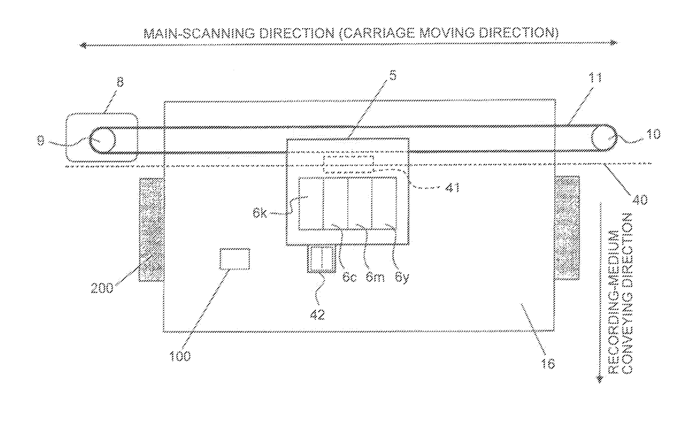
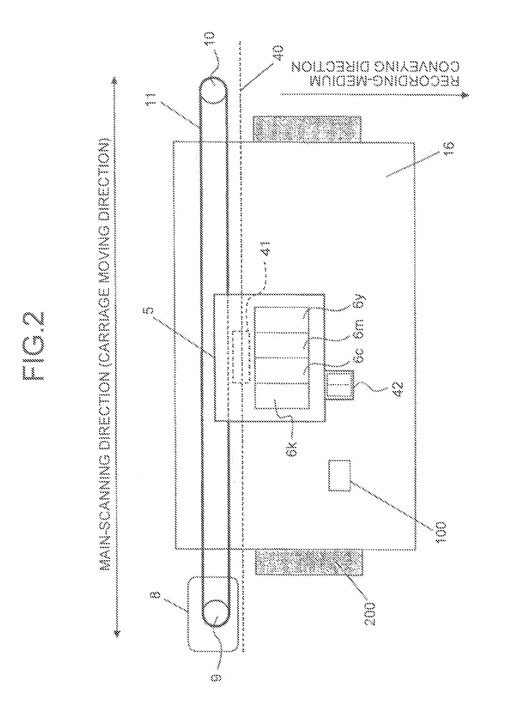
[0042]As illustrated in FIG. 2, the recording apparatus according to the first embodiment includes an image capturing unit 42 (image capturing device) mounted on a carriage 5. As illustrated in FIGS. 4A to 4C, the image capturing unit 42 includes a housing 421; a reference pattern (corresponding to a reference chart 400), arranged in the housing 421, used for color measurement; a two-dimensional sensor 423 that captures an image of the reference pattern 400 at a part of an image capturing area and captures an image of a test pattern 100, which is an object, in the other part of the area; an image capturing lens 425 arranged on a first optical path between the two-dimensional sensor 423 and the reference pattern 400 and a second optical path between the two-dimensional sensor 423 and the test pattern 100 to cause the image o...

second embodiment

[0111]A second embodiment of the present invention will be described below. In the first embodiment, the image capturing unit 42 illustrated in FIGS. 4A to 4C causes the reference chart 400 and the test pattern 100 to be directly illuminated with the light from the light source 424 to capture the image of the reference chart 400 and the image of the test pattern 100.

[0112]However, in the configuration where the light from the light source 424 directly illuminates the reference chart 400 and the test pattern 100, because the distance from the light source 424 to the reference chart 400 and the distance from the light source 424 to the test pattern 100 differ from each other, illuminance on the surface of the reference chart 400 can be different from illuminance on the test pattern 100. In a condition where the illuminance on the surface of the reference chart 400 is different from the illuminance on the test pattern 100, accuracy in color measurement of the test pattern 100 undesirab...

third embodiment

[0116]An outline of a recording apparatus according to a third embodiment of the present invention will be described with reference to FIGS. 20 and 21.

[0117]As illustrated in FIG. 20, the recording apparatus according to the third embodiment includes an image capturing unit 2042 (image capturing device) mounted on the carriage 5. As illustrated in FIG. 21, the image capturing unit 2042 is configured to include a housing 2421; a reference pattern (corresponding to the reference chart 400) used for color measurement and arranged in the housing 2421; a two-dimensional sensor 2423 that captures an image of the reference pattern 400 in one part of an image capturing area and captures an image of the test pattern 100, which is an object, in another part of the image capturing area; an image capturing lens 2425 arranged on a first optical path between the two-dimensional sensor 2423 and the reference pattern 400 and a second optical path between the two-dimensional sensor 2423 and the test...


PUM


Abstract

An image capturing device includes: a housing; a reference pattern used for color measurement and arranged in the housing; an image capturing element that captures an image of the reference pattern in a first area and an image of an object in a second area of the image capturing area; an image forming element causing the image of the reference pattern and the image of the object to be formed on the image capturing element by being arranged on a first optical path between the image capturing element and the reference pattern and a second optical path between the image capturing element and the object; and an optical member that guides any one of the images of the reference pattern and the object formed by the image forming element so that the images are to be formed on an element surface of the image capturing element.

Description

CROSS-REFERENCE TO RELATED APPLICATIONS[0001]The present application claims priority to and incorporates by reference the entire contents of Japanese Patent Application No. 2010-208370 filed in Japan on Sep. 16, 2010 and Japanese Patent Application No. 2010-208381 filed in Japan on Sep. 16, 2010.BACKGROUND OF THE INVENTION[0002]1. Field of the Invention[0003]The present invention relates to an image capturing device to be mounted on a recording apparatus, such as an inkjet printer, and a recording apparatus including the image capturing device.[0004]2. Description of the Related Art[0005]A typical inkjet recording apparatus ejects ink from a recording head mounted on a carriage while the carriage is reciprocating in the main-scanning direction (direction in which the carriage moves) to cause the ink to stick to a recording medium placed on a supporting plate, thereby recording an image (dots) on the recording medium. The recording apparatus conveys the recording medium in the sub-sc...

Claims


Application Information

Patent Timeline
Patent Type & Authority Applications(United States)
IPC IPC(8): H04N1/46
CPCG06K15/027H04N1/6044B41J29/393
Inventor SATOH, NOBUYUKIKOBAYASHI, MASALOTAKI, NORIKAZUHORIKAWA, DAISAKU
Owner RICOH KK
Why Eureka
Try Eureka