Diverter Valve

Active Publication Date: 2012-03-29
PROCESSING TECH
View PDF11 Cites 13 Cited by
  • Summary
  • Abstract
  • Description
  • Claims
  • Application Information

AI Technical Summary

Benefits of technology

[0008]The present invention provides a novel, improved valve for diverting between two different extruded materials to swap the material sent to different parts of a mold block, where the purity of the material sent t

Problems solved by technology

It should be appreciated, however, that swapping connections can result in bleed over and mixing of materials in the lines between the extruder assemblies and the mold.
Suc

Method used


Image

  • Diverter Valve
  • Diverter Valve
  • Diverter Valve

Examples


Example

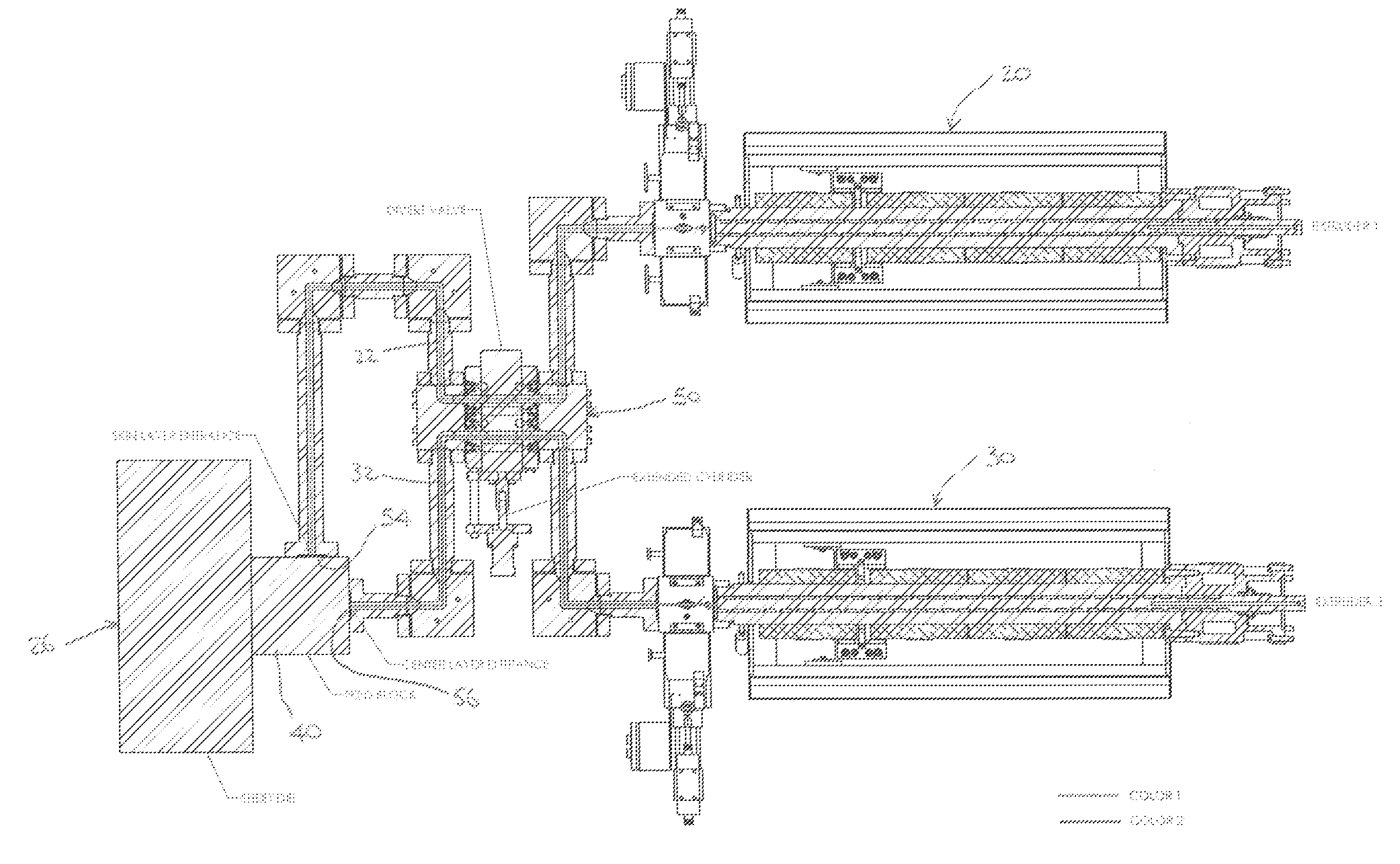
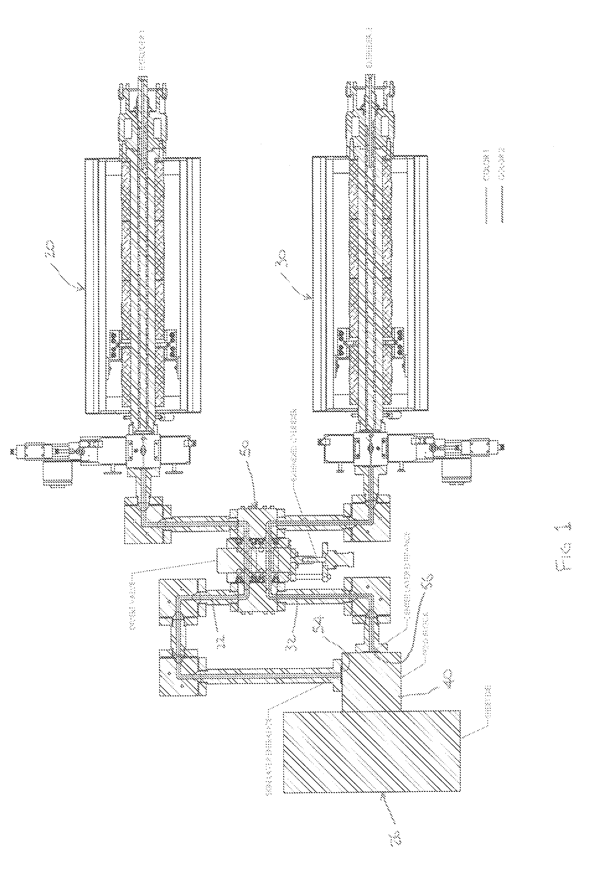
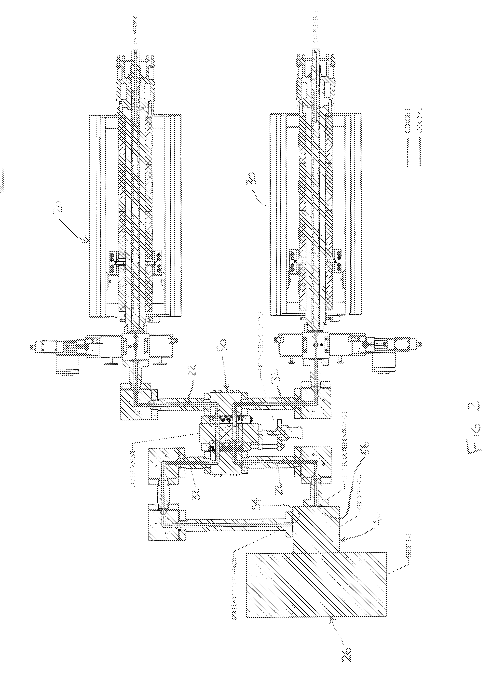
[0026]While this invention is susceptible of embodiment in many different forms, this specification and the accompanying drawings disclose only one specific form as an example of the use of the invention. The invention is not intended to be limited to the embodiment so described, and the scope of the invention will be pointed out in the appended claims.

[0027]For ease of description, the apparatus operating in accordance with this invention is described in the normal (upright) operating position, and terms such as upper, lower, horizontal, etc., are used with reference to this position.

[0028]The apparatus of this invention can have certain conventional components and control mechanisms the details of which, although not fully illustrated or described, will be apparent to those having skill in the art and an understanding of the necessary functions of such components and mechanisms.

[0029]Some of the Figures illustrating the preferred embodiment of the apparatus of the present inventio...


PUM

PropertyMeasurementUnit
Flow rateaaaaaaaaaa
Diameteraaaaaaaaaa
Widthaaaaaaaaaa

Abstract

A diverter valve controls input of two different extruded materials to a mold. A valve body has an axially extending opening, and a valve piston is axially movable in the opening between first and second positions. The body defines a first inlet for receiving a first material, and a second inlet for receiving a second material with first and second outlets opposite the inlets. A first flushing channel communicates with the first inlet and end ports, a second flushing channel communicates with the second inlet and end ports, and a third flushing channel opposite the first two communicates with the second outlet and includes a plurality of ports, with all the ports, inlets and outlets open to the axial opening. The piston has first and second through channels and first and second cross-over channels, each with inlet side and outlet side ports. In the first position, the first through channel connects the first inlet with the first outlet and the second through channel connects the second inlet with the second outlet, the valve piston blocks the end ports of the first flushing channel, and the first and second cross-over channels connect the second and third flushing channels to allow flow of material therein from the second inlet. In the second position, the first cross-over channel connects the first inlet with the second outlet and the second cross-over channel connects the second inlet with the first outlet, the valve piston blocks the end ports of the first flushing channel, and the first and second through channels connect the first and third flushing channels to allow flow of material therein from the first inlet.

Description

CROSS REFERENCE TO RELATED APPLICATION(S)[0001]Not applicable.STATEMENT REGARDING BACKGROUND OF THE INVENTION AND TECHNICAL PROBLEMS POSED BY THE PRIOR ART[0002]Molding of extruded materials to form countless products is widely done. As is well known, an extruder is used to provide the extruded material to a suitable die in which the extruded material is shaped to create the desired object. Commonly, the object which is created has a uniform continuous shape, such as conduits, pipes and flat sheets.[0003]Extruded sheets, for example, may be formed from many different materials, with many different thicknesses, and with different layer constructions. An extruded sheet may be formed by itself or combined with one or more other sheet layers that are concurrently formed, or combined after formation. In a typical apparatus for extrusion forming of sheet products, a roll stand is placed downstream of an extruder assembly with an associated sheet die. Flowable material is delivered from on...

Claims


Application Information

Patent Timeline
IPC IPC(8): F16K11/078B29C48/03B29C48/19B29C48/21B29C48/49B29C48/495
CPCB29C47/062B29C47/065B29C47/0816B29C47/56B29C47/0009B29C2947/92647B29C2947/92904F16K11/07F16K11/078B29C2947/92628Y10T137/86879Y10T137/4259Y10T137/86549B29C48/2556B29C48/19B29C48/21B29C48/03B29C2948/92628B29C2948/92647B29C2948/92904B29C48/495B29B7/801B29C48/49
Inventor HANSON, DANA R.GRITZNER, MITCHELL L.
Owner PROCESSING TECH
Why Eureka
Try Eureka