

Systems and methods for isolating parts
- Summary
- Abstract
- Description
- Claims
- Application Information
AI Technical Summary
Benefits of technology
Problems solved by technology
Method used
Image

Examples
Embodiment Construction
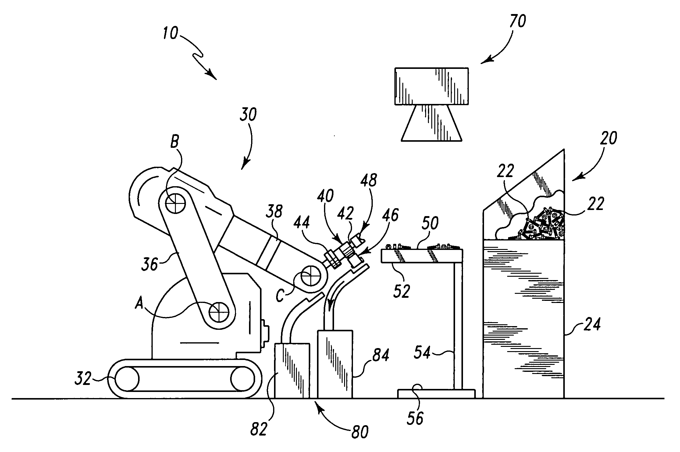
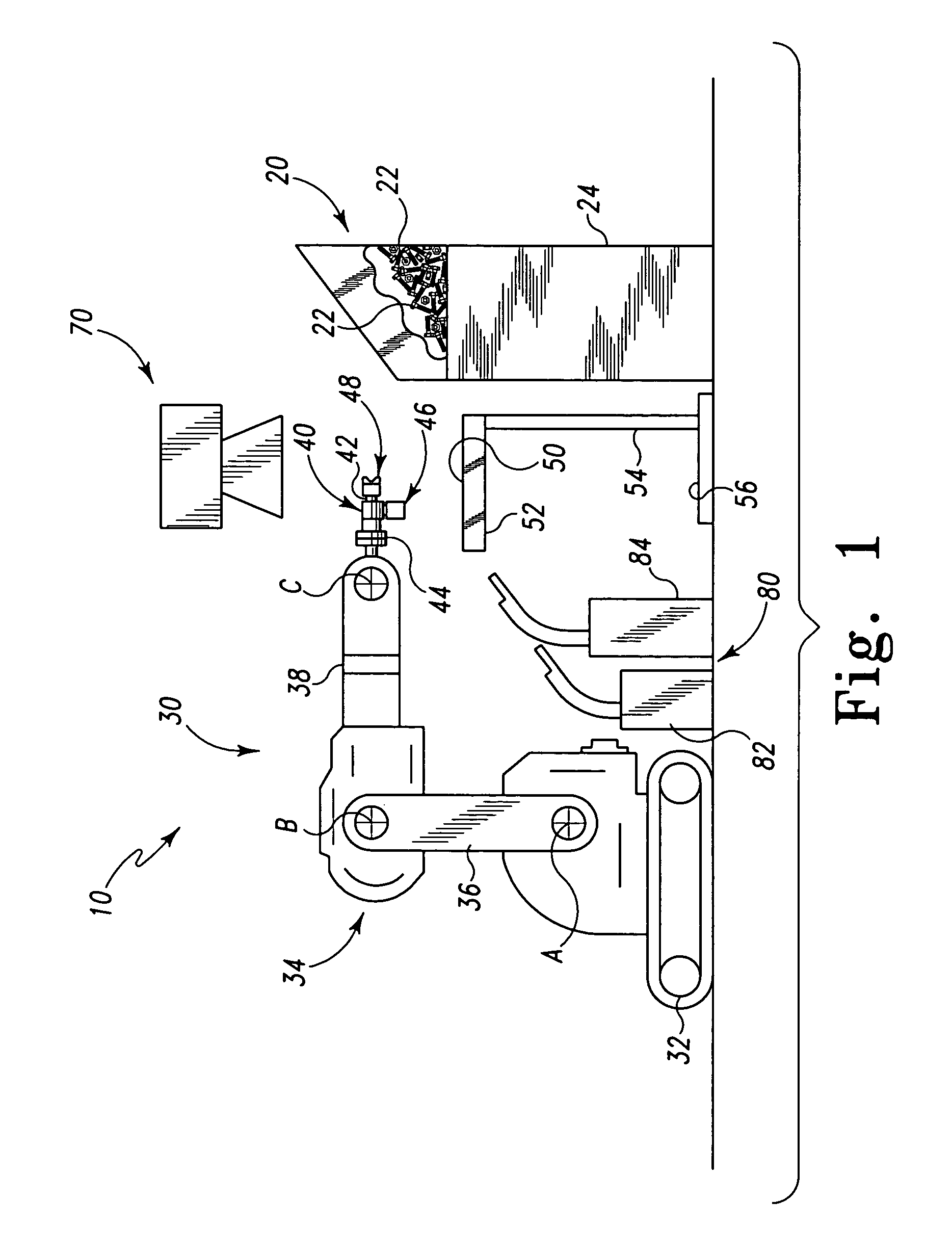
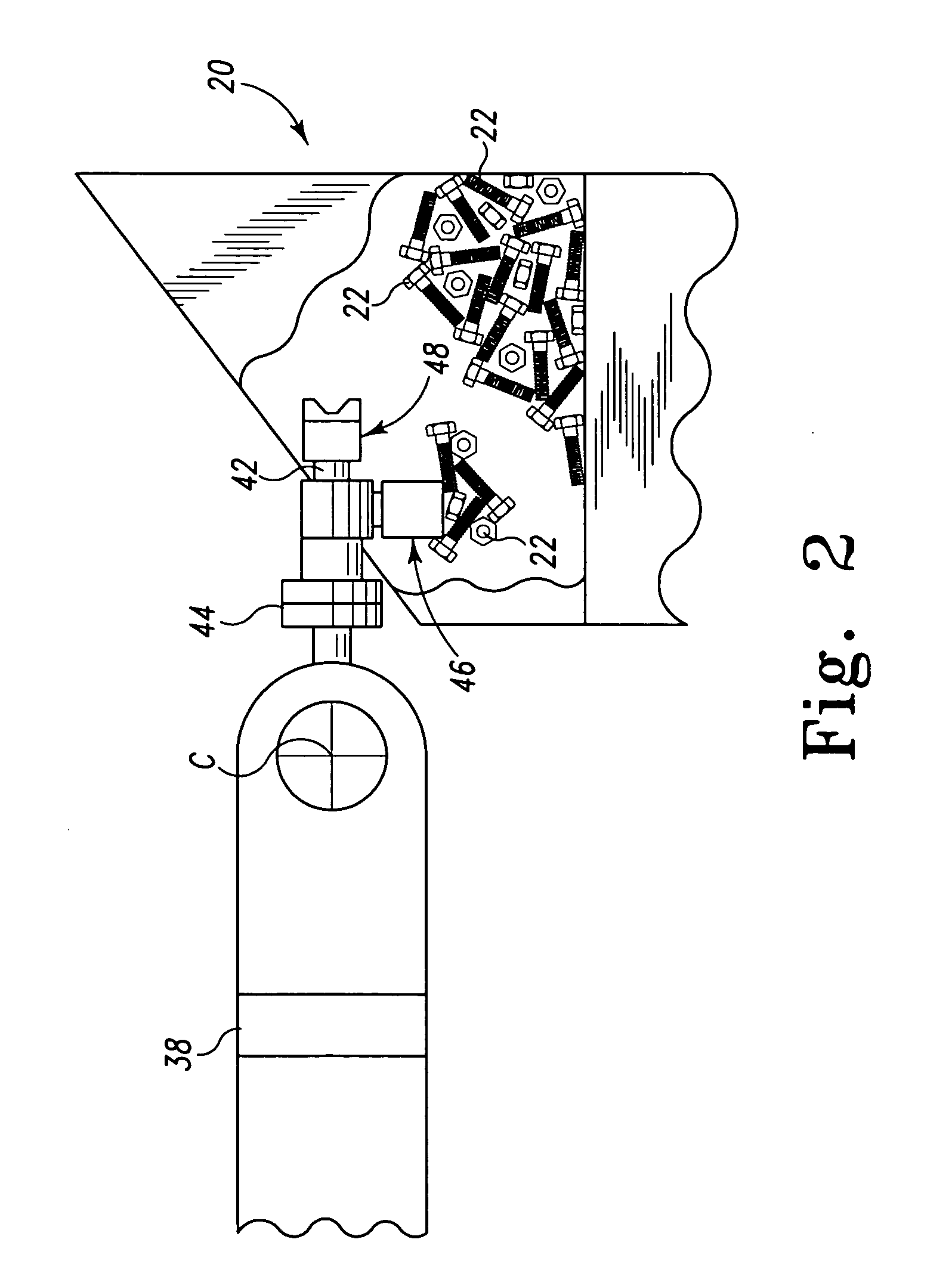
[0016] Referring to the drawing figures in detail, wherein corresponding numerals indicate the corresponding elements throughout the drawing figures, FIG. 1 illustrates a part isolation system 10 for separating a variety of parts. As illustrated, part isolation system 10 may comprise a receptacle 20, a picking assembly 30, an identification surface 50 and a vision system 70. As illustrated, the receptacle 20 may include a plurality of production parts 22 such as, for example, nuts, bolts and castings mixed together in a single barrel or box 24. Receptacle may be configured so that parts 22 are moved toward the top of barrel 24 for easy access by the loader assembly 40 such as by, for example, a weight-controlled hydraulic bottom plate associated with receptacle. As will be discussed, in one embodiment, the picking assembly 30 (e.g. including loader assembly 40) may be configured to remove a plurality of varying production parts 22 from the receptacle 24 for separation and transport ...
PUM
 Abstract
Description
Claims
Application Information