Rechargeable electric tool

a rechargeable electric tool and battery technology, applied in the direction of manufacturing tools, portable power-driven tools, drilling pipes, etc., can solve the problems of insufficient waterproof properties of the battery mounting part and the battery pack, and achieve the effect of convenient positioning

Active Publication Date: 2012-03-29
MAKITA CORP
View PDF5 Cites 27 Cited by
  • Summary
  • Abstract
  • Description
  • Claims
  • Application Information

AI Technical Summary

Benefits of technology

[0016]In addition, the elastic members are pressed into and brought into contact with the covering member to seal the surfaces of the covering member facing the elastic members. Accordingly, there is no gap between the covering member and the elastic members, and the rainwater or the like can be prevented from flowing toward the battery pack along the covering member.
[0017]According to the third aspect of the present invention, even if the rainwater or the like having entered inside of the housing from the openings passes between an inner surface of the housing and the electric component and flows toward the seal member, the projection of the seal member can prevent the rainwater or the like from flowing back to the opening side, and the rainwater or the like can be prevented from flowing toward the passing hole. Accordingly, the rainwater or the like can be prevented from flowing toward a gap between the mounting part for the battery pack and the battery pack, and the battery pack along the lead line passing through the passing hole.
[0018]According to the fourth aspect of the present invention, the seal member is not shaken by being pressed between the both ribs, and the seal member can be prevented from being moved in the housing. Accordingly, the seal memb

Problems solved by technology

However, for example, in the case where such rechargeable electric tool is left outside during rain, the rainwater or the like occasionally enters the housing

Method used


Image

  • Rechargeable electric tool
  • Rechargeable electric tool
  • Rechargeable electric tool

Examples


first embodiment

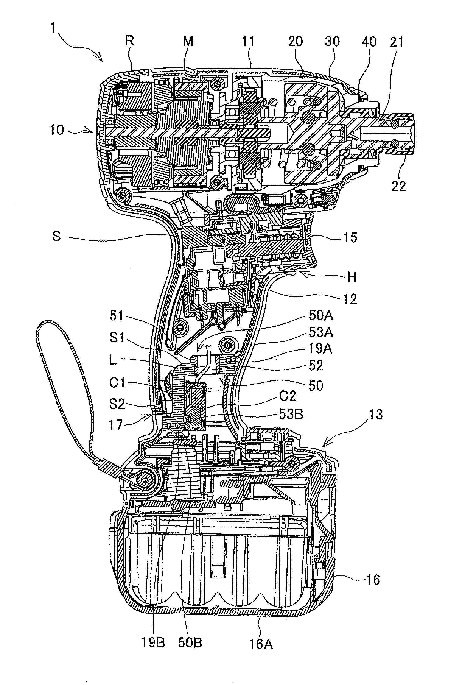
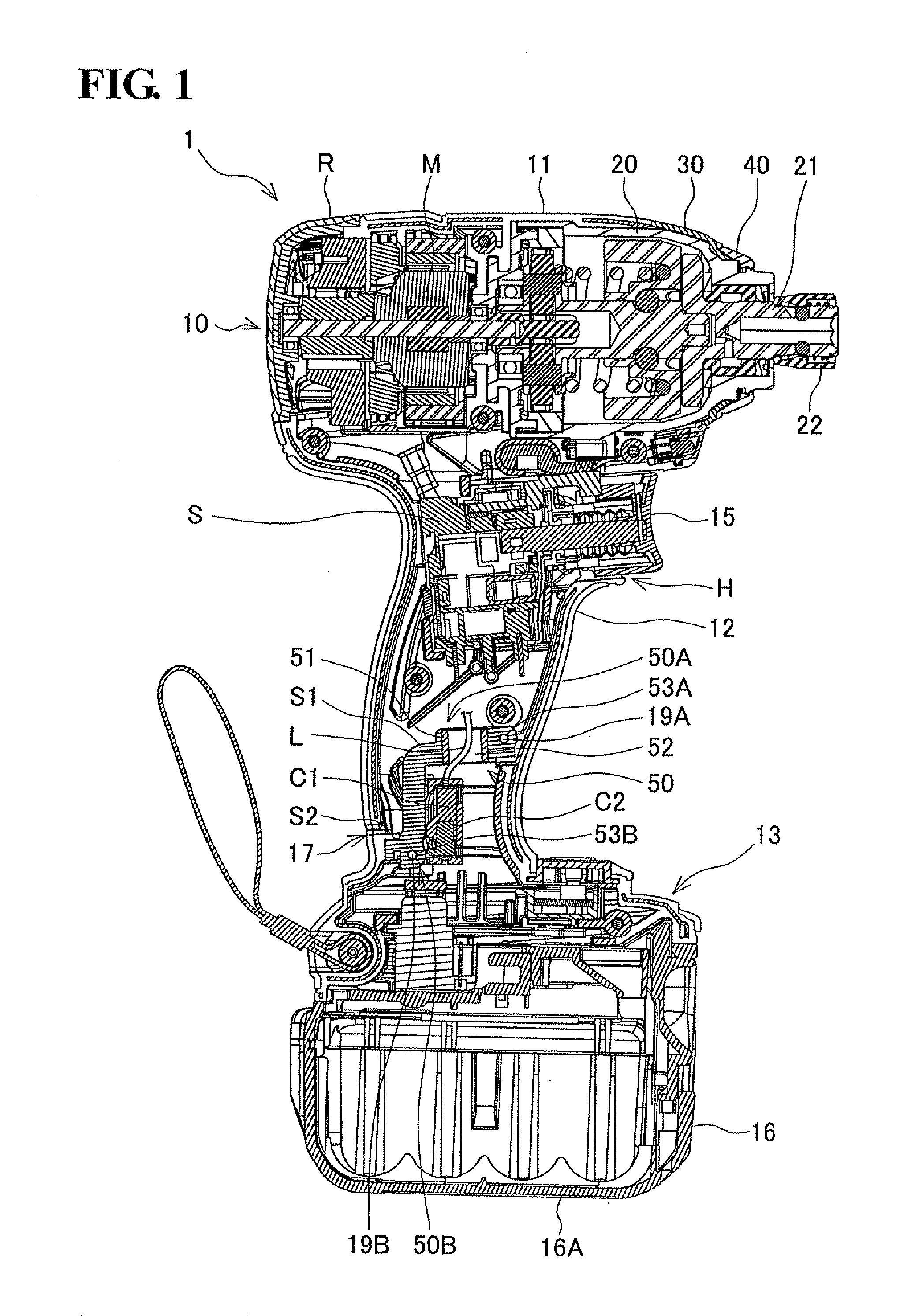
[0032]A first embodiment of the present invention will be described with reference to FIG. 1 to FIG. 3. As shown in FIG. 1, an impact driver 1 includes a main-body housing 10, a hammer case 20, a seal member 50, and the like.

[0033]As shown in FIG. 1 and FIG. 2, a main-body housing 10 is formed by combination of left and right half housings 10L and 10R made of resin, and includes a body 11, a handle part 12, a battery mounting part 13, and rear cover R. The body 11 is in a tubular shape and extends in the impact driver 1 in the vertical direction of FIG. 1. Inside of the body 11, a motor M is accommodated, and plural inlet ports 14A and outlet ports 14B (see FIG. 3) are provided at positions near the motor M. Further, the rear cover R formed in a tubular shape that is opened toward the body 11 is attached to a rear end of the body 11 by screwing. Plural inlet ports R1 (see FIG. 3) are provided even at the rear cover R, and these inlet ports 14A and R1 are used to draw in cooling air ...

second embodiment

[0052]A second embodiment of the present invention will be described with reference to FIG. 4 to FIG. 6. In the second embodiment, the same constitutional elements as those in the first embodiment are given the same reference numerals and the explanations thereof will not be repeated. In addition, the same effects as those in the first embodiment will not be repeated. Further, the lead line L is not illustrated in FIG. 4. However, the lead line L same as that in the first embodiment is also provided in an impact driver 1A of the second embodiment. The impact driver 1A includes a heat-shrinkable tube 55, single-bubble sponges 56 (56A and 56B), and a seal member 60. An inner circumferential surface of the heat-shrinkable tube 55 is coated with an adhesive. The heat-shrinkable tube 55 is heated after being mounted to the lead line L and a communication line L1, so that the heat-shrinkable tube 55 is shrunk and closely attached to the lead line L and the like. Accordingly, as shown in F...

third embodiment

[0058]A third embodiment of the present invention will be described with reference to FIG. 7 and FIG. 8. In the third embodiment, the same constitutional elements as those in the first and second embodiments are given the same reference numerals and the explanations thereof will not be repeated. Unlike the first and second embodiments, an impact driver 1B of the third embodiment has a body 11A formed in a tubular shape without providing the rear cover R. The impact driver 1B is provided with a seal member 70. The seal member 70 is made of elastic material such as rubber. As shown in FIG. 7, the seal member 70 is fitted into a position in the handle part 12 between the inlet port 14A and the opening H, and the battery pack 16 in a state where the seal member 70 is twisted around an outer circumferential surface of the switch S. Accordingly, the seal member 70 seals between the side where the inlet port 14A and the opening H are located and the battery pack 16-side in the handle part ...


PUM


Abstract

The present invention provides a rechargeable electric tool in which a battery pack detachably mounted to a mounting part, which is formed lower than an opening provided at a housing, wherein a seal member is held in the housing to seal between the opening and the battery pack mounted to the mounting part. A projection projecting toward the opening side is provided at the seal member, and a passing hole that penetrates the projection and the seal member and allows a lead line connecting an electric component accommodated on the opening side in the housing to the battery pack to pass therethrough is formed.

Description

BACKGROUND OF THE INVENTION[0001]This application claims the entire benefit of Japanese Patent Application Number 2010-217589 filed on Sep. 28, 2010 and Japanese Patent Application Number 2011-002143 filed on Jan. 7, 2011, the entirety of which is incorporated by reference.TECHNICAL FIELD[0002]The present invention relates to a rechargeable electric tool in which a battery pack serving as an electric power source is detachably mounted to a mounting part formed lower than openings provided at a housing.BACKGROUND ART[0003]For example, Japanese Patent Application Laid-Open Publication No. 2009-78322 discloses a rechargeable electric tool in which a battery pack is detachably mounted to a battery mounting part a grip part. The grip part is continuously provided at a housing in which a motor, a driving mechanism, and the like are mounted.[0004]In general, a hole is provided at a housing to expose a trigger of a switch necessary for electrical operations or / and a ventilation hole is prov...

Claims


Application Information

Patent Timeline
IPC IPC(8): B25F5/02
CPCB25F5/02
Inventor NAGASAKA, HIDENORIKUMAGAI, RYUNOSUKE
Owner MAKITA CORP
Why Eureka
Try Eureka