Image forming system

Inactive Publication Date: 2012-03-29
OKI DATA CORP
View PDF4 Cites 3 Cited by
  • Summary
  • Abstract
  • Description
  • Claims
  • Application Information

AI Technical Summary

Benefits of technology

[0012]As described above, according to the aspect of the present invention, the upper device includes the service style table unit and the service style deployment unit. Accordingly, it is possible to set the service setting value to the image forming apparatus all at once.

Problems solved by technology

In the conventional image forming system disclosed in Patent Reference, when the number of setting items increases, for example, when a function is added, it is difficult to set the setting items easily.

Method used


Image

  • Image forming system
  • Image forming system
  • Image forming system

Examples


first embodiment

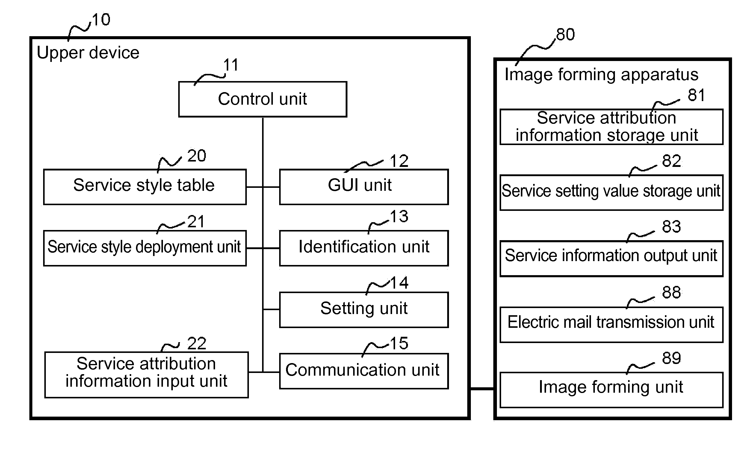
[0026]A first embodiment of the present invention will be explained. FIG. 1 is a block diagram showing a configuration of an image forming system according to the first embodiment of the present invention.

[0027]As shown in FIG. 1, the image forming system includes an image forming apparatus 80 and an upper device 10 connected to the image forming apparatus 80 through a communication path to be capable of communicating with each other.

[0028]In the embodiment, the upper device 10 includes a control unit 11; a GUI (Graphic User Interface) unit 12; an identification unit 13; a setting unit 14; a communication unit 15; a service style table 20; a service style deployment unit 21; and a service attribution information input unit 22.

[0029]In the embodiment, the control unit 11 is provided for controlling an entire operation of the upper device 10. The GUI unit 12 includes a screen portion for displaying an operation screen and an input portion for receiving an input of a user. The identifi...

second embodiment

[0049]A second embodiment of the present invention will be explained next. FIG. 5 is a block diagram showing a configuration of an image forming system including a first upper device 10A according to the second embodiment of the present invention. Components shown in FIG. 5 and similar to those shown in FIG. 1 in the first embodiment are designated with the same reference numerals.

[0050]As shown in FIG. 5, the image forming system in the second embodiment includes the first upper device 10A different from the upper device 10 in the first embodiment and an image forming apparatus 80A different from the image forming apparatus 80 in the first embodiment. The first upper device 10A is connected to the image forming apparatus 80A through a communication path to be capable of communicating with each other.

[0051]In the second embodiment, in addition to the configuration of the upper device 10 in the first embodiment, the first upper device 10A includes a confirmation unit 16; a service st...


PUM


Abstract

An image forming system includes an image forming apparatus and an upper device connected to the image forming apparatus through a communication path. The upper device includes a service attribution information input unit for inputting service attribution information containing service identification information; a service style table unit for containing a plurality of service styles each formed of a service setting value; and a service style deployment unit for selecting the service style according to the service identification information. The image forming apparatus includes a service attribution information storage unit for storing the service attribution information; and a service setting value storage unit for storing the service setting value. The service style deployment unit selects the service style when the service attribution information is input. Then, the upper device transmits the service setting value and the service attribution information to the image forming apparatus.

Description

BACKGROUND OF THE INVENTION AND RELATED ART STATEMENT[0001]The present invention relates to an image forming system. More specifically, the present invention relates to an image forming system including an image forming apparatus and an upper device.[0002]In a conventional image forming system, an upper device is configured to set an image forming apparatus through a network.[0003]Patent Reference has disclosed such a conventional image forming system, in which it is possible to input administrator identification information through a simplified method when an administrator sets or updates an image forming apparatus or an option of the image forming apparatus.[0004]Patent Reference Japanese Patent Publication No. 2006-72500[0005]In the conventional image forming system disclosed in Patent Reference, when the number of setting items increases, for example, when a function is added, it is difficult to set the setting items easily.[0006]In view of the problems described above, an objec...

Claims


Application Information

Patent Timeline
IPC IPC(8): G06K15/02
CPCG06F3/1204G06F3/1231G06K15/402G06K15/1805G06K15/002
Inventor TAKIGUCHI, MITSURU
Owner OKI DATA CORP
Why Eureka
Try Eureka