Consistent Interpretation Method On Carrier Indication Field and Related Communication Device

Inactive Publication Date: 2012-03-29
HTC CORP
View PDF7 Cites 6 Cited by
  • Summary
  • Abstract
  • Description
  • Claims
  • Application Information

AI Technical Summary

Problems solved by technology

However, there is no consistent interpretation on CIF at both the eNB and the UEs.

Method used


Image

  • Consistent Interpretation Method On Carrier Indication Field and Related Communication Device
  • Consistent Interpretation Method On Carrier Indication Field and Related Communication Device
  • Consistent Interpretation Method On Carrier Indication Field and Related Communication Device

Examples


Embodiment Construction

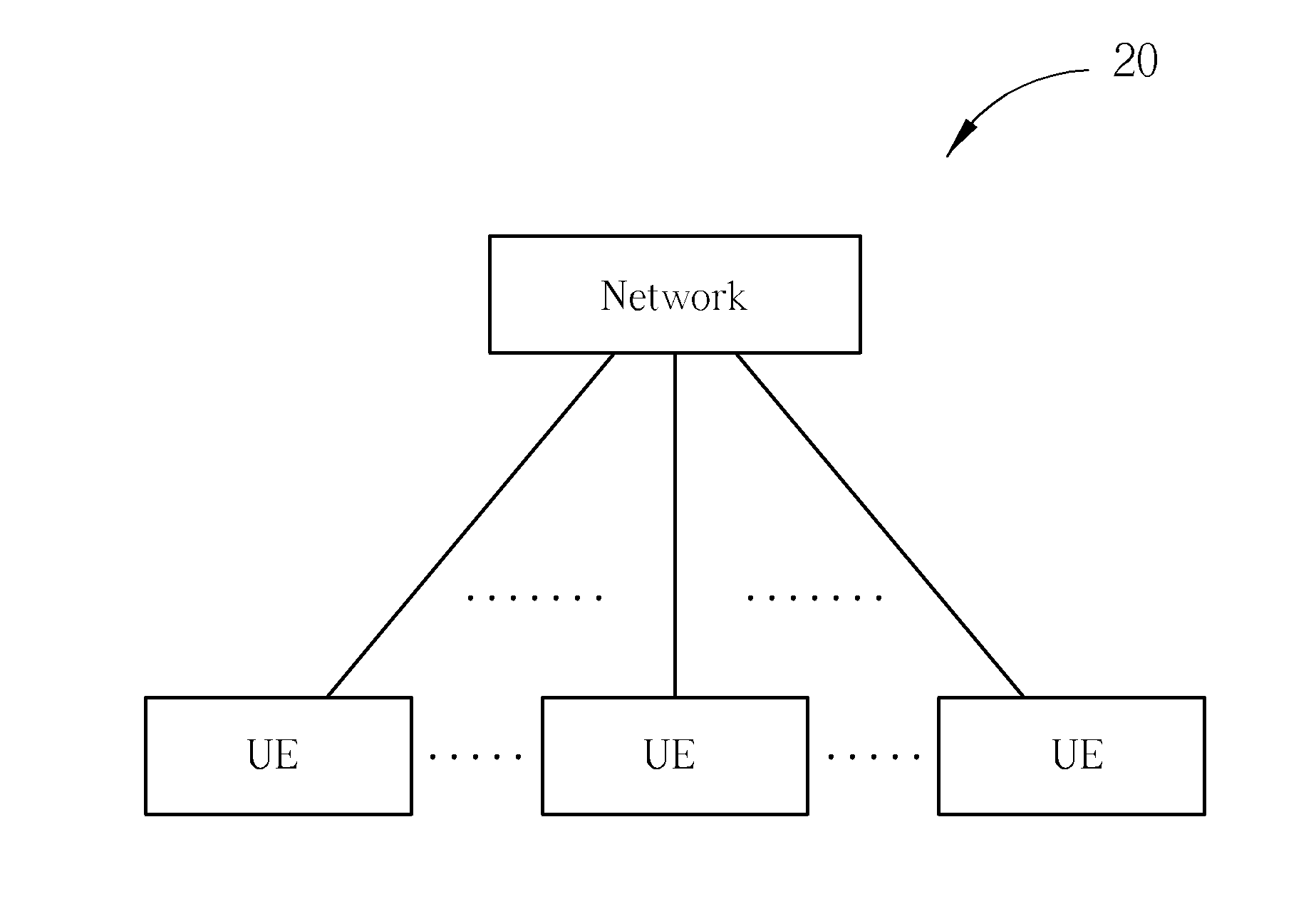
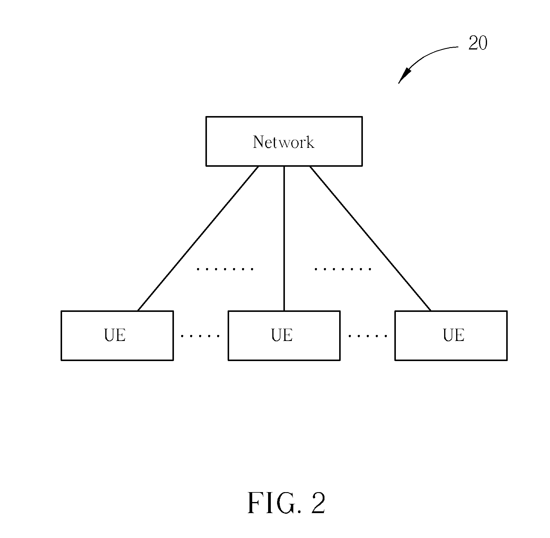
[0018]Please refer to FIG. 2. FIG. 2 is a schematic diagram of a wireless communication system 20 of the present disclosure. The wireless communication system 20 can be an LTE-Advanced system, or other mobile communication systems (e.g. LTE, WCDMA, HSPA, GSM, EDGE, etc.). The wireless communication system 20 is briefly composed of a network and a plurality of user equipments (UEs), as the structure illustrated in FIG. 2. In the LTE-Advanced system, the network is referred as an evolved universal terrestrial radio access network (E-UTRAN) comprising a plurality of evolved base stations (eNBs). The UEs can be devices such as mobile phones, computer systems, etc. Besides, the network and the UE can be seen as a transmitter or receiver according to transmission direction, e.g., for uplink (UL), the UE is the transmitter and the network is the receiver, and for downlink (DL), the network is the transmitter and the UE is the receiver.

[0019]Please refer to FIG. 3. FIG. 3 is a schematic dia...


PUM


Abstract

A consistent interpretation method on a carrier indication field (CIF) in a wireless communication system is disclosed. The method comprises building up a first common set of a plurality of component carriers between a mobile station and a base station according to a specific order; and addressing the plurality of component carriers according to the first common set. One CIF value corresponds to one of the plurality component carriers or be left unused.

Description

CROSS REFERENCE TO RELATED APPLICATIONS[0001]This application claims the benefit of U.S. Provisional Application No. 61 / 320,330, filed on Apr. 2, 2010 and entitled “Method and Apparatus for Carrier Indication, Index, and Addressing in Communication Systems”, the contents of which are incorporated herein.BACKGROUND OF THE INVENTION[0002]1. Field of the Invention[0003]The application relates to a method used in a wireless communication system and related communication device, and more particularly, to a consistent interpretation method on a carrier indication field in a wireless communication system and related communication device.[0004]2. Description of the Prior Art[0005]A long-term evolution (LTE) system, initiated by the third generation partnership project (3GPP), is now being regarded as a new radio interface and radio network architecture that provides a high data rate, low latency, packet optimization, and improved system capacity and coverage. In the LTE system, an evolved u...

Claims


Application Information

Patent Timeline
IPC IPC(8): H04W92/00
CPCH04L5/001H04L5/0094H04L5/008
Inventor LI, CHI-FANG
Owner HTC CORP
Why Eureka
Try Eureka