Stand alone intervertebral fusion device

a technology of intervertebral fusion and fusion device, which is applied in the field of stand alone intervertebral fusion device, can solve the problems of patient discomfort, dysphasia and/or dysphonia, and especially difficult for the cervical spin

Inactive Publication Date: 2012-03-29
DEPUY SYNTHES PROD INC
View PDF13 Cites 198 Cited by
  • Summary
  • Abstract
  • Description
  • Claims
  • Application Information

AI Technical Summary

Benefits of technology

[0028]The in-line insertion of the angled fixation device allows for a smaller incision and access site for the spacer and angled fixation device, and also allows the surgeon to avoid having to insert the f...

Problems solved by technology

This reluctance stems from the observation that the anterior plate can be situated too proud and so its profile can sometimes cause patient discomfort and cause dysphasia and/or dysphonia.
This can be especially difficult for the cervical spine, as the surgeon needs to either deliver the screw down into the inferior vertebral body but may be obstructed by the patient's chin, or deliver the screw up into the superior vertebral body but may be obstructed by the patient's sternum.
However, the faceplate that holds the screws is not designed to be implanted in the disc space, but rather cloak...

Method used


Image

  • Stand alone intervertebral fusion device
  • Stand alone intervertebral fusion device
  • Stand alone intervertebral fusion device

Examples


Embodiment Construction

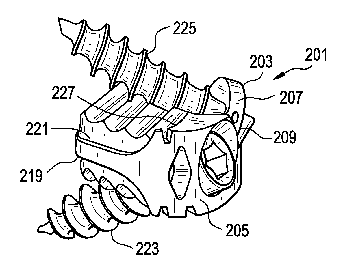
[0063]For the purposes of the present invention, a “cage” is the spacer of the present invention without the anterior wall. That is, the cage consists essentially of the posterior wall and the first and second side walls. The anterior wall may also be referred to as a “faceplate”.

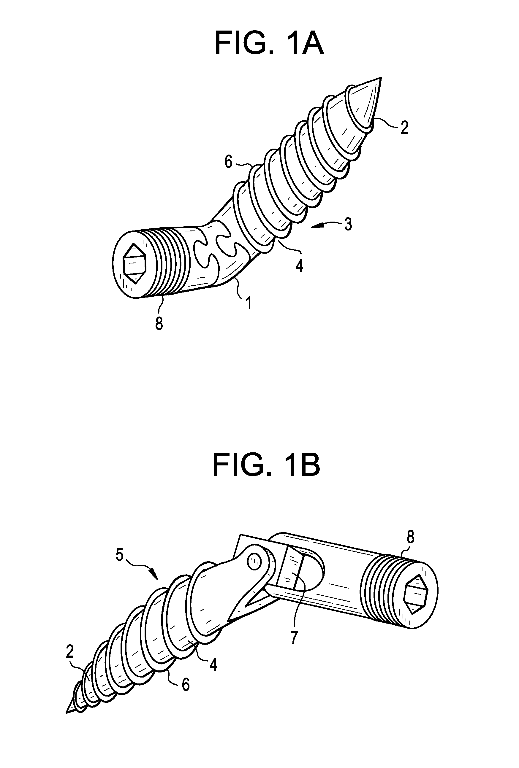
[0064]Now referring to FIG. 1A, in some embodiments, there is provided a first screw 3 having a distal tip 2 an intermediate shaft 4 having a threadform 6 thereon, and a proximal head 8. The angled shaft portion 1 of the first screw 3 is made of a flexible material. Now referring to FIG. 1B, in other embodiments, there is provided a second screw 5 having a distal tip 2 an intermediate shaft 4 having a threadform 6 thereon, and a proximal head 8. The angled shaft portion 7 includes a joint, such as a universal joint or a ball-and-socket joint.

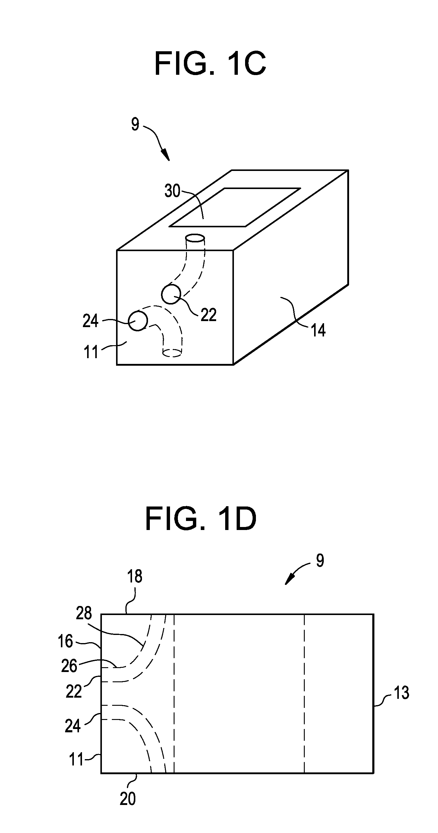
[0065]Now referring to FIGS. 1A-1F, there is provided an intervertebral device comprising:[0066]a) an intervertebral spacer 9 having an anterior wall 11, a posterior wa...


PUM


Abstract

An angled fixation device, such as an angled screw. This angled fixation device may be used by the surgeon to secure a spacer to a spinal disc space. The proximal end portion of the angled fixation device is driven perpendicular to the anterior wall of the spacer, and so is parallel to the vertebral endplates and in-line with the inserter. The distal end portion of the angled fixation device is oriented at about a 45 degree angle (plus or minus 30 degrees) to the vertebral endplate it enters.

Description

CONTINUING DATA[0001]This application claims priority from U.S. Ser. No. 61 / 385,959, filed on Sep. 23, 2010, and entitled “Stand Alone Intervertebral Fusion Device” (DEP6341USPSP), the specification of which is incorporated by reference in its entirety.[0002]This application claims priority from U.S. Ser. No. 61 / 466,309, filed on Mar. 22, 2011, and entitled “Novel Implant Inserter Having a Laterally-Extending Dovetail Engagement Feature” (DEP6392USPSP), and is related to non-provisional U.S. Ser. No. ______, filed on even date, entitled “Novel Implant Inserter Having a Laterally-Extending Dovetail Engagement Feature” (DEP6392USNP), the specifications of which are incorporated by reference in their entireties.[0003]This application claims priority from U.S. Ser. No. 61 / 466,321, filed on Mar. 22, 2011, and entitled “Fusion Cage with In-Line Single Piece Fixation” (DEP6394USPSP), and is related to non-provisional U.S. Ser. No. ______, filed on even date, entitled “Fusion Cage with In-L...

Claims


Application Information

Patent Timeline
IPC IPC(8): A61F2/44
CPCA61B17/8625A61B17/8685A61F2/30744A61F2/4465A61F2/447A61F2002/2835A61F2002/30266A61F2002/30281A61F2002/3038A61F2002/30387A61F2002/30405A61F2002/30472A61F2002/305A61F2002/30504A61F2002/30514A61F2002/30576A61F2002/30578A61F2002/30604A61F2002/30607A61F2002/30616A61F2002/30736A61F2002/30787A61F2002/30841A61F2002/30843A61F2002/30904A61F2002/4475A61F2310/00179A61F2310/00293A61B17/8047A61B17/8052A61B2017/00004A61F2/4455A61F2220/0016A61F2230/0073A61F2002/30331A61F2002/30433A61F2002/30593A61F2002/30517A61F2/4611A61F2002/4615A61F2/442
Inventor GAMACHE, THOMASCHILDS, JOSEPHSHAW, DEREKHOWE, JONATHANGORHAN, MICHAELSTAD, SHAWNFLAHERTY, KEVIN
Owner DEPUY SYNTHES PROD INC
Why Eureka
Try Eureka