Yarn feeding device and yarn feeding method for knitting machine

a feeding device and knitting machine technology, applied in knitting, textiles and papermaking, instruments, etc., can solve the problems of reducing yarn tension, high tension peak of yarn, cutting yarn, etc., and achieves the effect of reducing the fluctuations in yarn tension caused by the changes in yarn speed, preventing yarn from cutting, and reducing the number of yarns

Active Publication Date: 2012-04-05
SHIMA SEIKI MFG LTD
View PDF0 Cites 0 Cited by
  • Summary
  • Abstract
  • Description
  • Claims
  • Application Information

AI Technical Summary

Benefits of technology

[0021]According to the present invention, yarn tension fluctuations caused by the changes in yarn speeds are reduced with controlling the torque to the buffer at plural sections in the knitting course. The torque is controlled in accordance with the yarn speed obtained based on the knitting data, namely, the speed of the yarn supplied from the buffer on the basis of the knitting data. Thus, the control is not a feed back control based on the tensions, but the torque is controlled by a feedforward control, which does not cause a delay because of a sensor and the torque generator. Thus, even when knitting a knitted fabric at a high yarn speed of, for example, 7 m / sec or above, the yarn tension can be made almost constant. As a result, even when performing high-speed knitting or knitting using a weak yarn, the yarn may be prevented from cutting. Preventing the yarn tension fluctuations can also prevent the sizes of stitches from fluctuating. Note that, in this specification, the descriptions about the yarn feeding device apply to the yarn feeding method, and the descriptions about the yarn feeding method apply to the yarn feeding device. The knitting data are data stored in the knitting machine for performing knitting. The knitting speed may be added annually or by default when supplying data containing the knitting speed from the start or after supplying data that do not containing the knitting speed.
[0022]It is preferred that the yarn feeding device for a knitting machine be provided with a sensor for detecting a rotation angle of the buffer, and that the torque controller corrects the torque obtained by the conversion unit, such that the rotation angle falls within a predetermined range. When the yarn is fed out at yarn speeds by a servomotor for feeding out the yarn, the rotation angle should be constant. Correcting the torques to make the rotation angles constant can also correct errors in the amount of yarn to be fed.
[0023]It is more preferred that the conversion unit has a table for obtaining the torque as a function of the yarn speed, and correction unit for correcting the torque obtained from the table such that the torque becomes smaller at a section where the yarn speed increases than other sections, for example, where the speed increases sharply. In this manner, the total number of knitting needles operating the yarn reaches a maximum value, and the tension peak that is caused when the course knitting shifts from a knitting-start section to a knitting-middle section can be eliminated or reduced. Therefore, the yarn can be prevented from cutting or becoming tight even when knitting at high speeds.
[0024]Providing a plurality of the tables depending on a target yarn tension can allow knitting with an appropriate tension in accordance with a knitting operation using a yarn that easily or hardly cuts or a knitting operation using a single yarn or two-fold yarn.

Problems solved by technology

When knitting at high speed, however, it has been found that simply controlling the amount of yarn to be fed might cause a high tension peak to the yarn and consequently cut the yarn.
However, when a sufficient amount of the excess yarn is reeled out beforehand, the yarn tension lowers, and consequently the yarn becomes loose.
For these reasons, it is difficult to reduce the yarn tension fluctuations when knitting at speeds higher than the speeds assumed in Patent Documents 1 and 2.
However, according to the experiments by the present inventors, the feedback control has been found not enough to prevent the high tension peak at high speed knitting.
The yarn tension peak caused small stitches where the loop lengths thereof were reduced, and sometimes the yarns were cut because the tension of the yarns exceeded their durability.

Method used


Image

  • Yarn feeding device and yarn feeding method for knitting machine
  • Yarn feeding device and yarn feeding method for knitting machine
  • Yarn feeding device and yarn feeding method for knitting machine

Examples


embodiments

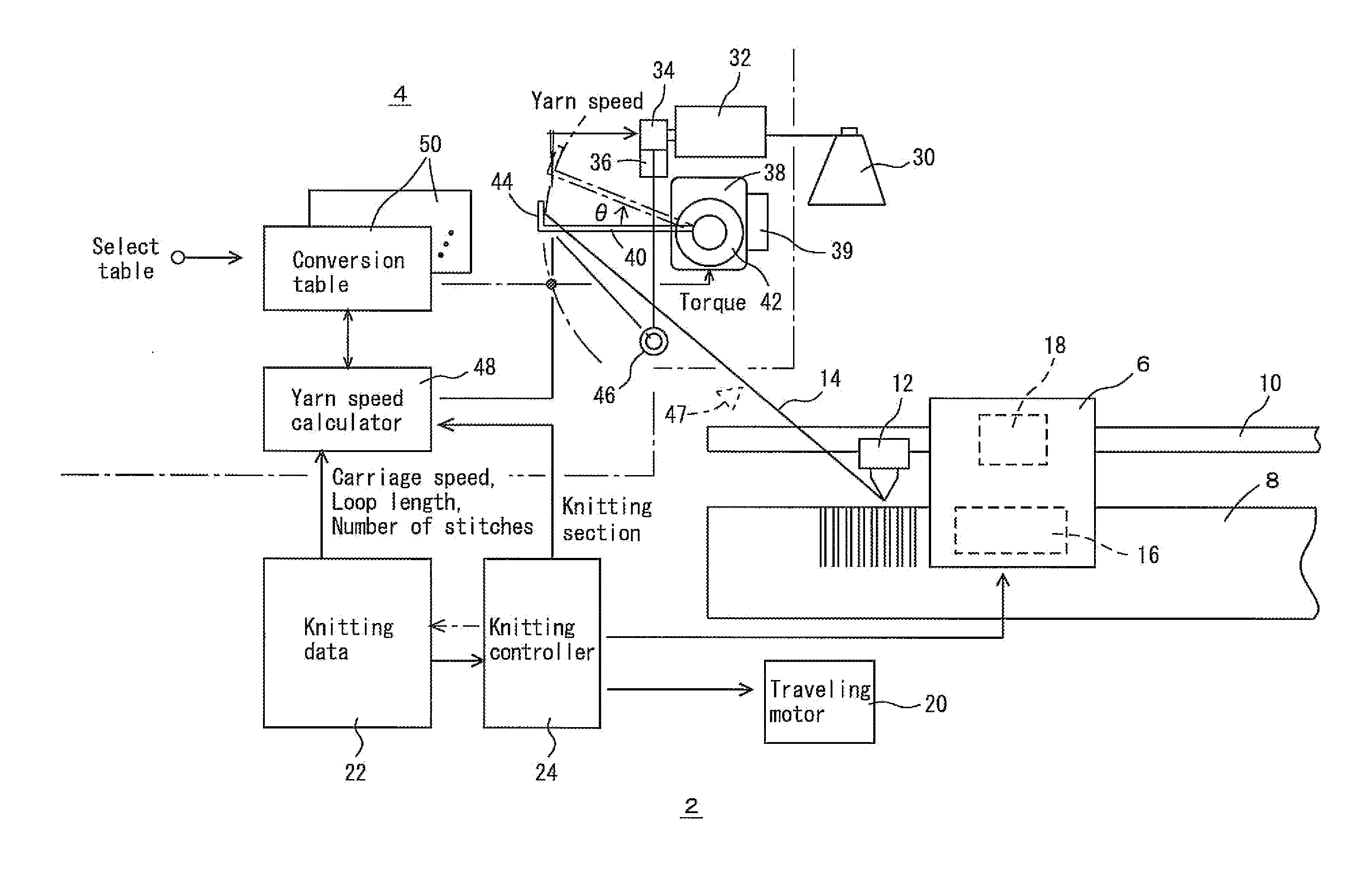
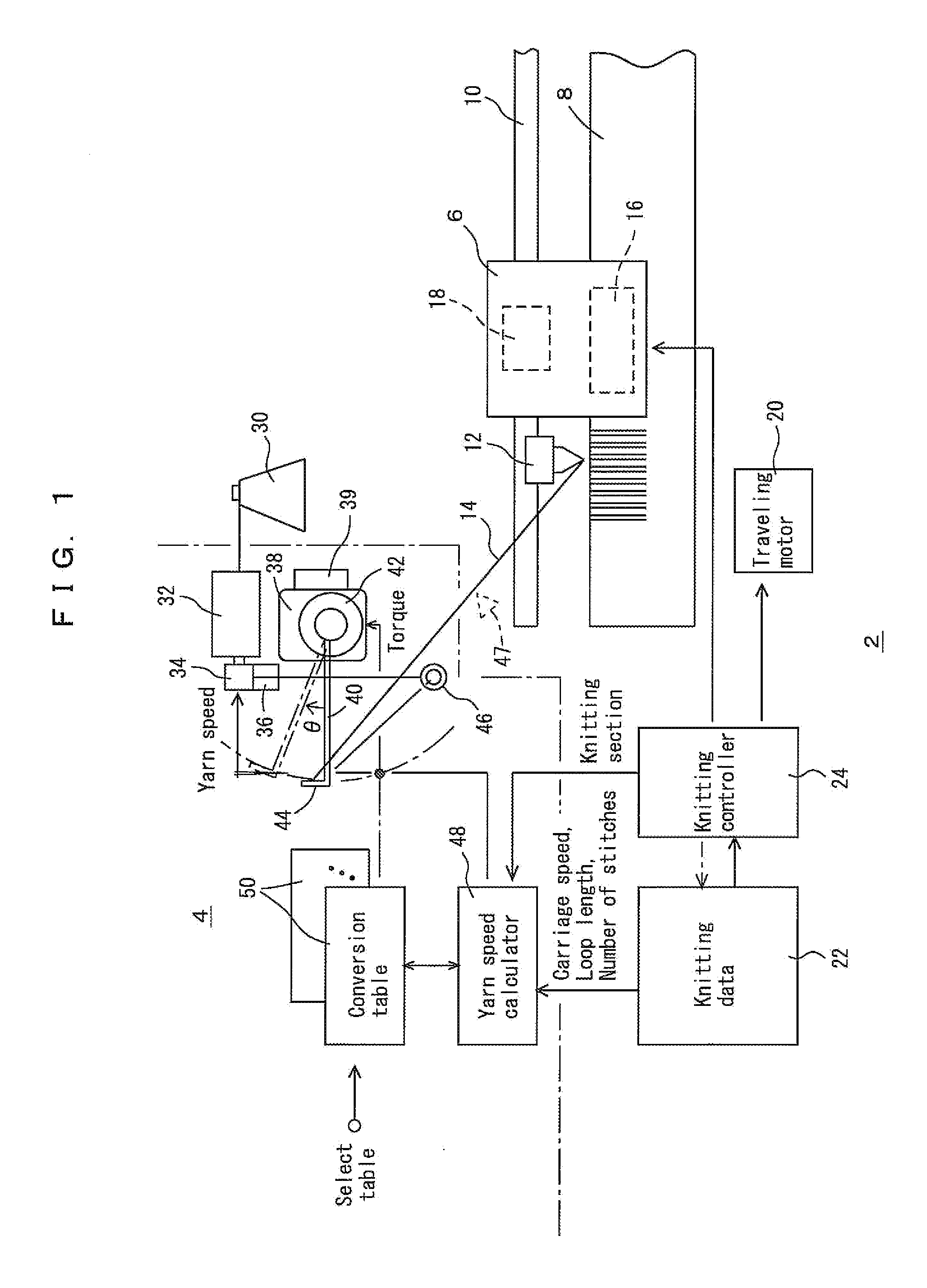
[0036]An embodiment of supplying yarns from the left-hand side to a flat-knitting machine is illustrated in FIGS. 1 to 9, but the yarns may be supplied from above or the right-hand side. In these diagrams, reference numeral 2 represents a flat-knitting machine body, which may be a circular knitting machine body, and 4 a yarn feeding device. In the embodiment, the yarn feeding device 4 is integrated with the flat-knitting machine, but the yarn feeding device 4 may be independent of the flat-knitting machine body 2. Hereinafter, the flat-knitting machine body 2 is simply referred to as “flat-knitting machine 2.” The flat-knitting machine 2 has a carriage 6 and one or two pairs of needle beds 8. Carriers 12, which are moved along carrier rails 10, are operated by, for example, the carriage 6, to supply yarns 14 to knitting needles of the needle beds 8.

[0037]The carriage 6 has a needle selecting device 16 to select which knitting needles of the needle beds 8 to drive, and performs knitt...


PUM


Abstract

A yarn feeding device for a knitting machine comprises a motor for driving a roller from which a yarn is fed out, and a rotatable arm which intermediately stores the yarn fed out from the roller, and the yarn is fed from the arm to a knitting machine body. A torque generator is provided to apply a variable torque to the arm. A yarn speed is obtained from a loop length of a stitch for each knitting needle and a knitting speed calculated on the basis of knitting data used in the knitting machine body. The yarn speed is converted into a torque to be applied to a buffer using a conversion table at each knitting section in a knitting course so as to correct a yarn tension fluctuation caused by the yarn speed, and the torque generator is controlled in accordance with the torque thus obtained. The yarn tension fluctuation is reduced so that high-speed knitting and knitting using a weak yarn can be facilitated.

Description

TECHNICAL FIELD[0001]The present invention relates to improvement of a yarn feeding device and a yarn feeding method for supplying a yarn to a knitting machine such as a flat-knitting machine or a circular knitting machine.BACKGROUND ART[0002]The inventors have proposed a yarn feeding device for feeding a yarn of required length using a servomotor in accordance with a knitting section to be knitted, and supplying the yarn to a carrier of a knitting machine by means of an arm functioning as a buffer (Patent Document 1: JP4016030B, Patent Document 2: JP 2006-169675A). The amount of yarn required per unit of time is referred to as “yarn speed” in this specification. The yarn speed is decided by a yarn length used for forming stitches and changes in the yarn length between the buffer arm and the needle bed that are caused by a motion of the carrier. The buffer arm is often simply called “arm.”[0003]According to Patent Documents 1 and 2, the arm is biased by a spring so as to provide a s...

Claims


Application Information

Patent Timeline
Patent Type & Authority Applications(United States)
IPC IPC(8): D04B15/44D04B15/48
CPCD04B15/48D04B15/38D04B15/44
Inventor NISHITANI, HIROKAZUKOMURA, YOSHIYUKI
Owner SHIMA SEIKI MFG LTD
Why Eureka
Try Eureka