Parallel robot

a robot and parallel technology, applied in the field of robots, can solve problems such as difficulty in control and maintenan

Inactive Publication Date: 2012-04-05
HONG FU JIN PRECISION IND (SHENZHEN) CO LTD +1
View PDF5 Cites 38 Cited by
  • Summary
  • Abstract
  • Description
  • Claims
  • Application Information

AI Technical Summary

Problems solved by technology

However, the typical parallel robot has a relatively complex construction and control system, thereby making it difficult to control and maintain.

Method used


Image

  • Parallel robot
  • Parallel robot
  • Parallel robot

Examples


Embodiment Construction

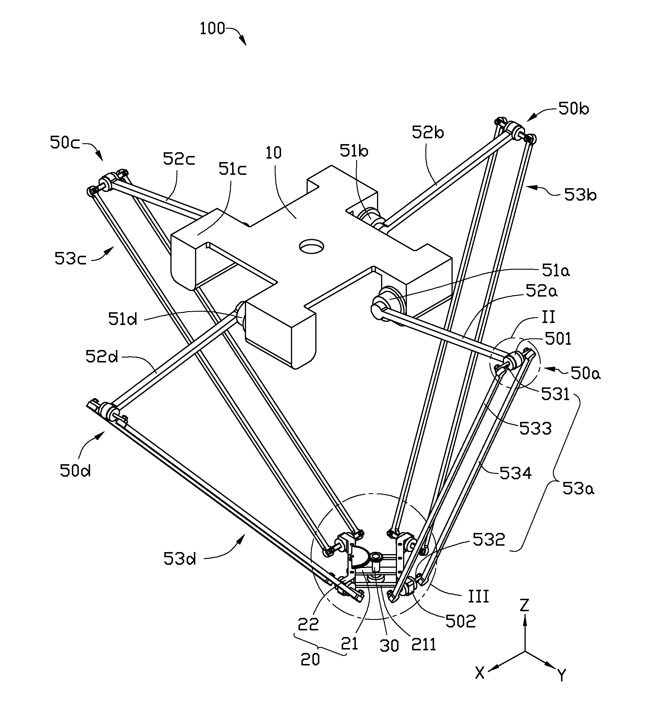
[0013]Referring to FIGS. 1 through 3, an embodiment of a parallel robot 100 is shown. The parallel robot 100 includes a base 10, a movable platform 20, an actuator 30 mounted on the movable platform 20, and four control arms 50a, 50b, 50c, 50d rotatably interconnecting the base 10 and the movable platform 20. The movable platform 20 can move along the X-axis, Y-axis, and Z-axis, and rotate about the Z-axis when controlled by the control arms 50a, 50b, 50c, 50d. The actuator 30 may be a gripper or a sucker.

[0014]In the illustrated embodiment, the base 10 is substantially rectangular The control arms 50a, 50b, 50c, 50d have the same structure, and are evenly arranged on a periphery of the base 10.

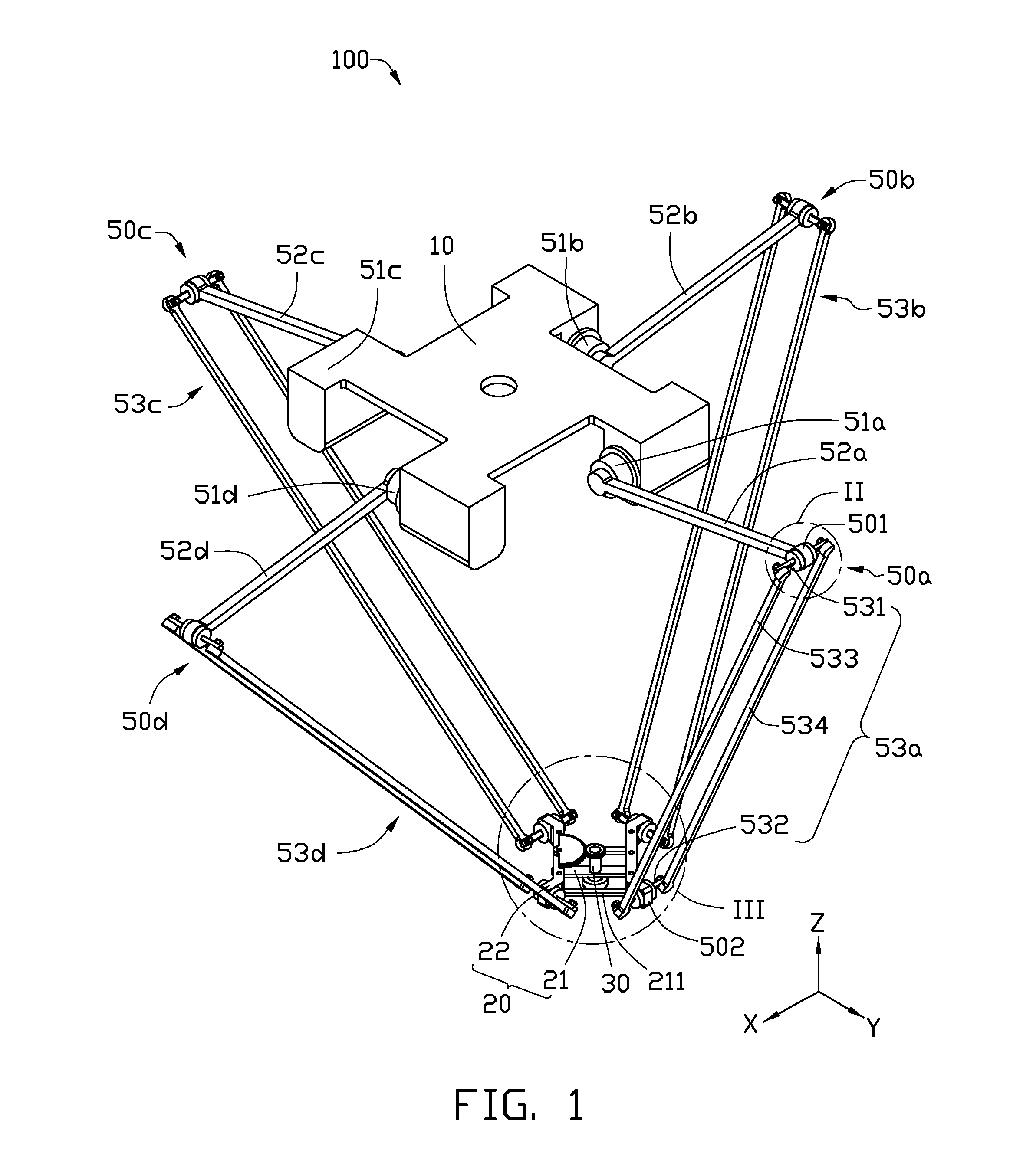
[0015]Taking the control arm 50a as an example, the control arm 50a includes a driving member 51a connected to the base 10, an action pole 52a driven by the driving member 51a, and a four-rod linkage assembly 53a interconnecting between the action pole 52a and the movable platform 20. In the ...


PUM


Abstract

A parallel robot includes a base, a movable platform, an actuator, and four control arms. The actuator is positioned on the movable platform. The control arms are interconnected between the base and the movable platform. Each control arm includes a driving member connected to the base, an action pole driven by the driving member, and a four-rod linkage assembly interconnected between the action pole and the movable platform. One end of the four-rod linkage assembly is connected to the action pole via a first rotary joint, and the other end of the four-rod linkage assembly is connected to the movable platform via a second rotary joint. An axis of the first rotary joint is substantially parallel to an axis of the second rotary joint.

Description

BACKGROUND[0001]1. Technical Field[0002]The present disclosure generally relates to robotics, and particularly, to a parallel robot having a simplified structure.[0003]2. Description of the Related Art[0004]Parallel robots have the advantages of stability, higher load-bearing capability, favorable weight to load ratio, and other dynamic characteristics among other things, and can be used in many fields.[0005]A commonly used parallel robot includes a base, a movable platform, and six control arms with two ends of the parallel robot pivotally connecting the movable platform and the base, respectively. Each control arm includes an actuator and a movable member driven by the actuator. When the movable members are cooperatively moved by the corresponding actuators, the movable platform can be moved to a predetermined position to realize a displacement having six degrees of freedom. However, the typical parallel robot has a relatively complex construction and control system, thereby makin...

Claims


Application Information

Patent Timeline
Patent Type & Authority Applications(United States)
IPC IPC(8): B25J17/00
CPCB25J9/0051Y10T74/20329B25J17/0216
Inventor LONG, BO
Owner HONG FU JIN PRECISION IND (SHENZHEN) CO LTD
Why Eureka
Try Eureka