MEMS actuator device deployment

a technology of actuators and actuators, applied in the direction of camera focusing arrangement, gearing, printers, etc., can solve the problems of large size, complexity and cost of actuators, and achieve the effect of small and simpl

Active Publication Date: 2012-04-05
DIGITALPTICS MEMS
View PDF3 Cites 56 Cited by
  • Summary
  • Abstract
  • Description
  • Claims
  • Application Information

AI Technical Summary

Benefits of technology

[0009]In accordance with the present disclosure, actuator devices for optical elements are provided which are substantially smaller and simpler than prior art actuator mechanisms, and which can be reliably implemented in miniature camera systems to achieve, among others, the same or better advanced features of higher-end camera systems, and in particular, OIS.

Problems solved by technology

The reason for this is due in large part to the larger size, complexity and cost of the actuators needed to effect relative movement of optical elements, such as lenses, image sensors and the like, in order to achieve such advanced effects.

Method used


Image

  • MEMS actuator device deployment
  • MEMS actuator device deployment
  • MEMS actuator device deployment

Examples


Embodiment Construction

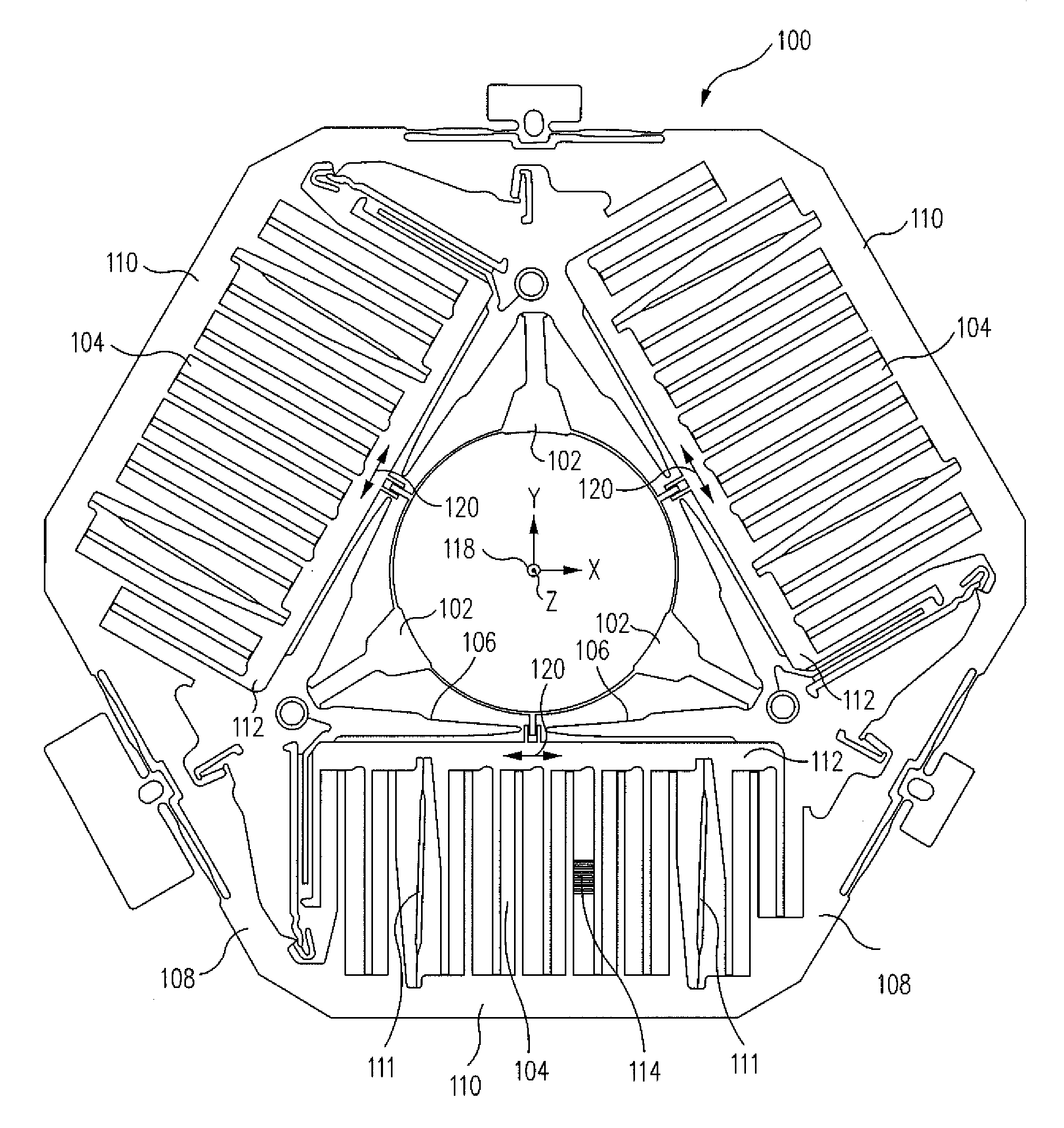
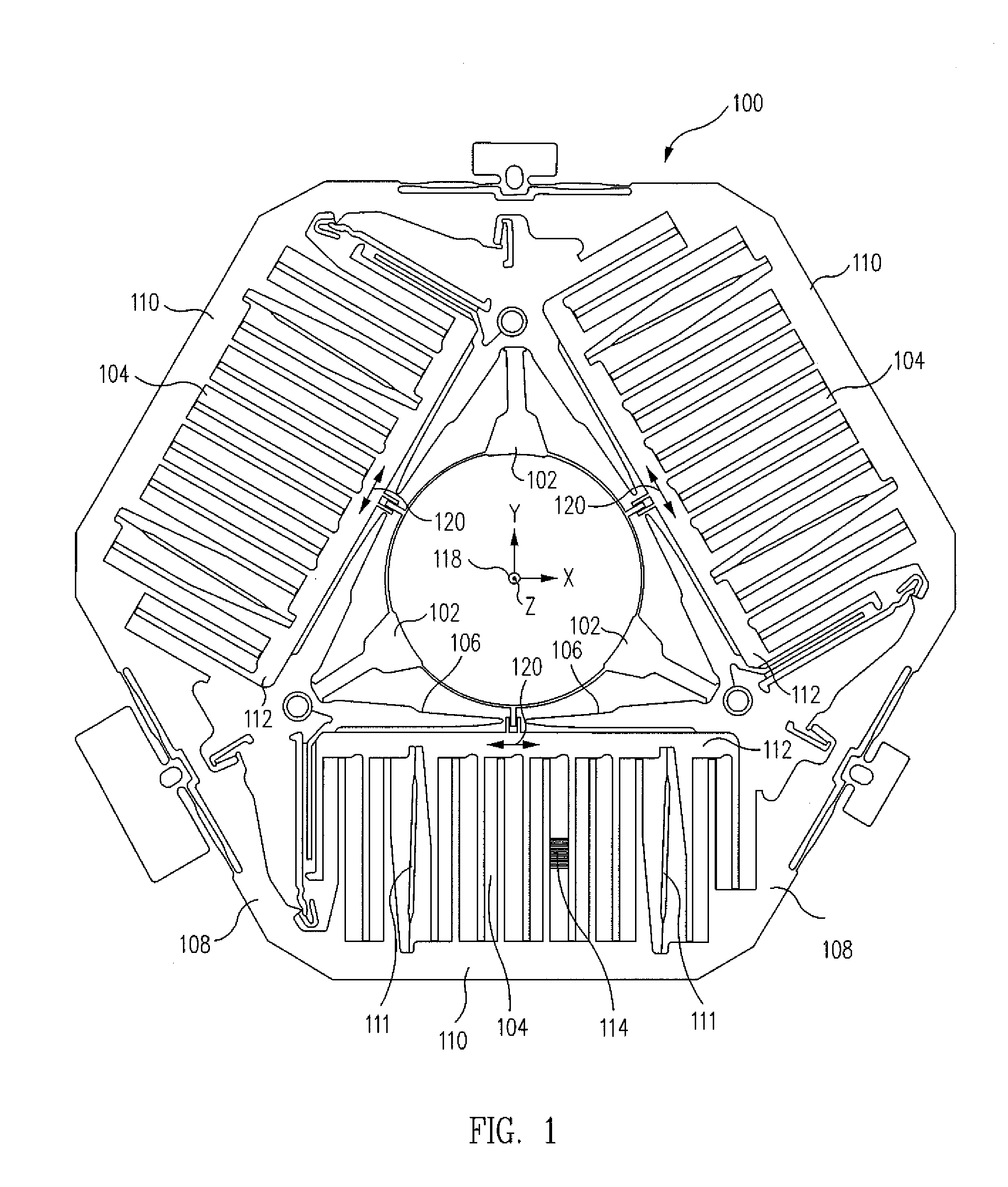
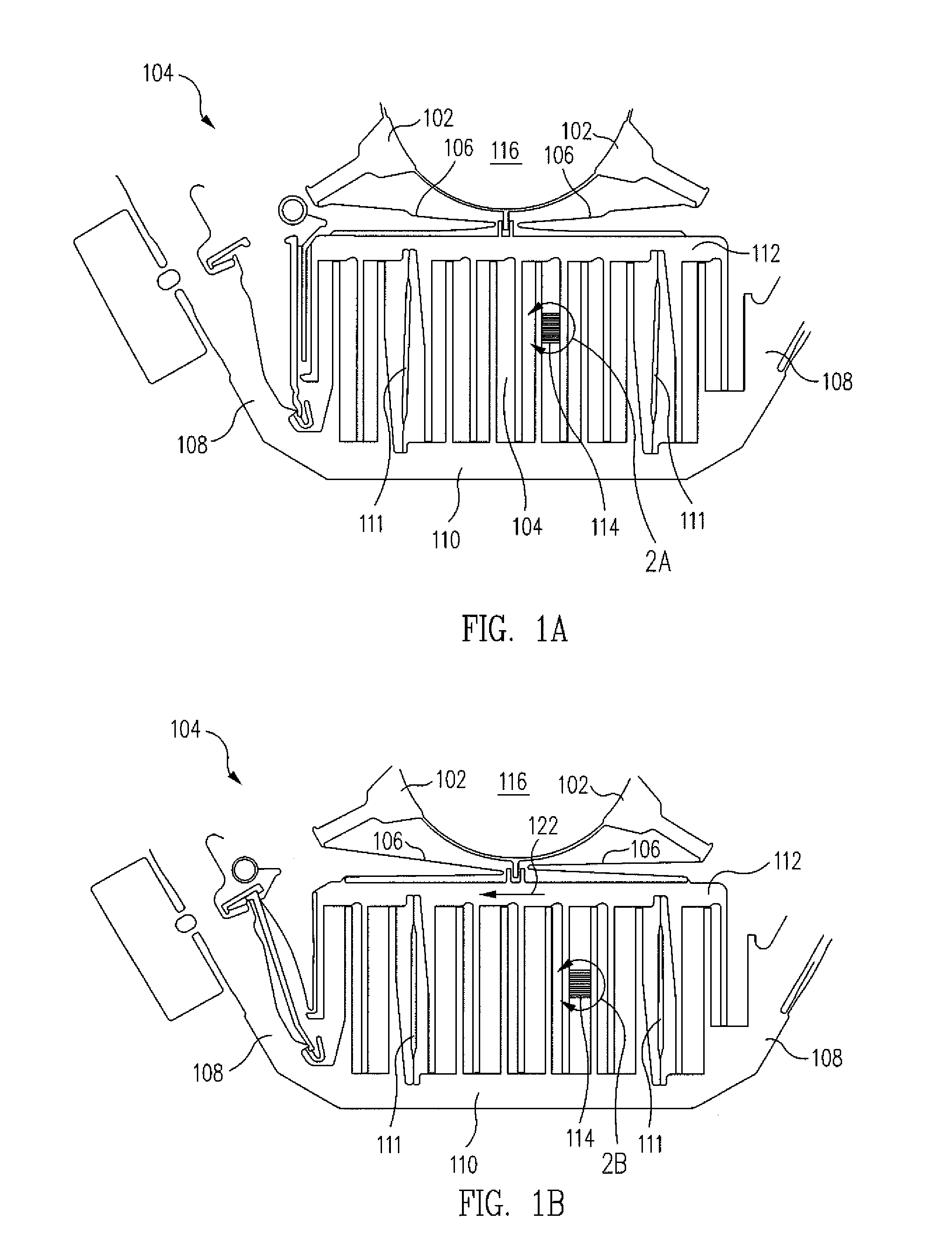
[0054]In the present disclosure, actuator devices are described that are useful for in-plane, out-of-plane, and both in-plane and out-of-plane actuation of, for example, optical elements of miniature cameras, together with methods for making and deploying them for operational use.

[0055]An example of an actuator device 100 adapted to effect movement of an optical element, such as a lens, lens group or an imaging sensor, in a focal plane, i.e., an X-Y plane orthogonal to an optical or Z axis, of a camera, is illustrated in the plan view of FIG. 1 and described in detail in commonly owned U.S. patent application Ser. No. ______, filed ______ and incorporated herein by reference. As illustrated in FIG. 1, in some embodiments, the generally planar actuator device 100 can comprise a stage 102 resiliently supported for movement within a plane of the device 100, three or more actuators 104, each coupled to an outer periphery of the stage 102 through at least one flexure 106 and operable to ...


PUM

PropertyMeasurementUnit
forceaaaaaaaaaa
distanceaaaaaaaaaa
resilientaaaaaaaaaa

Abstract

A method for making an actuator device includes forming a substantially planar structure having a stage resiliently supported for movement within a plane of the structure, an actuator coupled to an outer periphery of the stage and operable to apply a force acting in the plane and tangentially to the stage when actuated, the actuator comprising a fixed frame and a moving frame resiliently supported for reciprocal movement relative to the fixed frame by a motion control flexure, and an outer frame surrounding and supporting the stage and the actuator. The moving frame is moved to a deployed position that is coplanar with, parallel to and spaced apart from the fixed frame at a selected distance, and the moving frame is then fixed at the deployed position for substantially rectilinear, perpendicular movement relative to the fixed frame.

Description

RELATED APPLICATIONS[0001]This application is a continuation-in-part of U.S. patent application Nos. 12 / 846,670, 12 / 946,657 and 12 / 946,646, all filed Nov. 15, 2010 and incorporated herein by reference.BACKGROUND[0002]1. Technical Field[0003]This disclosure relates, in general, to actuator devices that are useful in optical devices, for example, cameras, particularly miniature cameras and the like, to effect relative movement of optical elements, such as lenses, filters, image sensors and the like, so as to achieve desirable optical effects, such as, for example, optical image stabilization (OIS).[0004]2. Related Art[0005]Actuators for use in miniature cameras and other optical devices are relatively well known. Such actuator devices typically comprise voice coil or Lorentz actuators that are used, for example, to move a lens for focusing, zooming, or OIS.[0006]Miniature cameras are frequently used in a variety of different electronic devices. For example, miniature cameras are commo...

Claims


Application Information

Patent Timeline
Patent Type & Authority Applications(United States)
IPC IPC(8): H04N5/232F16H21/44H05K7/00B23P11/00
CPCB81B3/0037B81B2201/033B81B2203/053G03B3/10Y10T74/18992G03B2205/0007G03B2205/0084Y10T29/49826G03B5/00
Inventor CALVET, ROBERT J.LIU, XIAOLEIJAIN, ANKURHARIHARAN, LAKSHMINARAYANGUTIERREZ, ROMAN C.
Owner DIGITALPTICS MEMS
Why Eureka
Try Eureka