Analyte-sensing device

an analyte and sensor technology, applied in the field of implantable sensors, can solve the problems of compromising measurement accuracy, low signal-to-background and signal-to-noise ratio, and difficult transdermal measurement of optical signals, so as to improve tissue penetration, eliminate crosstalk, and improve the effect of penetration

Active Publication Date: 2017-10-26
GLUSENSE LTD
View PDF3 Cites 7 Cited by
  • Summary
  • Abstract
  • Description
  • Claims
  • Application Information

AI Technical Summary

Benefits of technology

[0032]For some applications, the external reading unit comprises the first and the second wireless energy transmitters, which are configured to transmit the electromagnetic radiation at the first and the second RF frequencies, respectively, and thus activate the first and the second implantable-unit light sources, respectively. Typically, the first and the second wireless energy transmitter comprise respective different sized coils and/or different capacitors in order to tune the transmitters to their respective RF frequencies, thereby eliminating crosstalk between the transmitters.
[0033]For some applications, the implantable unit further comprises an upconversion material, which is disposed in a vicinity of the fluorescent sensor molecules. The at least one fluorescent moiety of the fluorescent sensor molecules is configured to be excited by light between a first absorption wavelength and a second absorption wavelength greater than the first absorption wavelength. The upconversion material is configured to produce emission of light having an emission peak wavelength between the first absorption wavelength and the secon

Problems solved by technology

Accurate transdermal measurement of optical signals is challenging in practice in part because of the properties of skin and other tissue between an implanted unit and an external reading unit.
Low transmission through the skin and other tissue may result in low signal-to-background and signal-to-noise ratios, compr

Method used


Image

  • Analyte-sensing device
  • Analyte-sensing device
  • Analyte-sensing device

Examples


Embodiment Construction

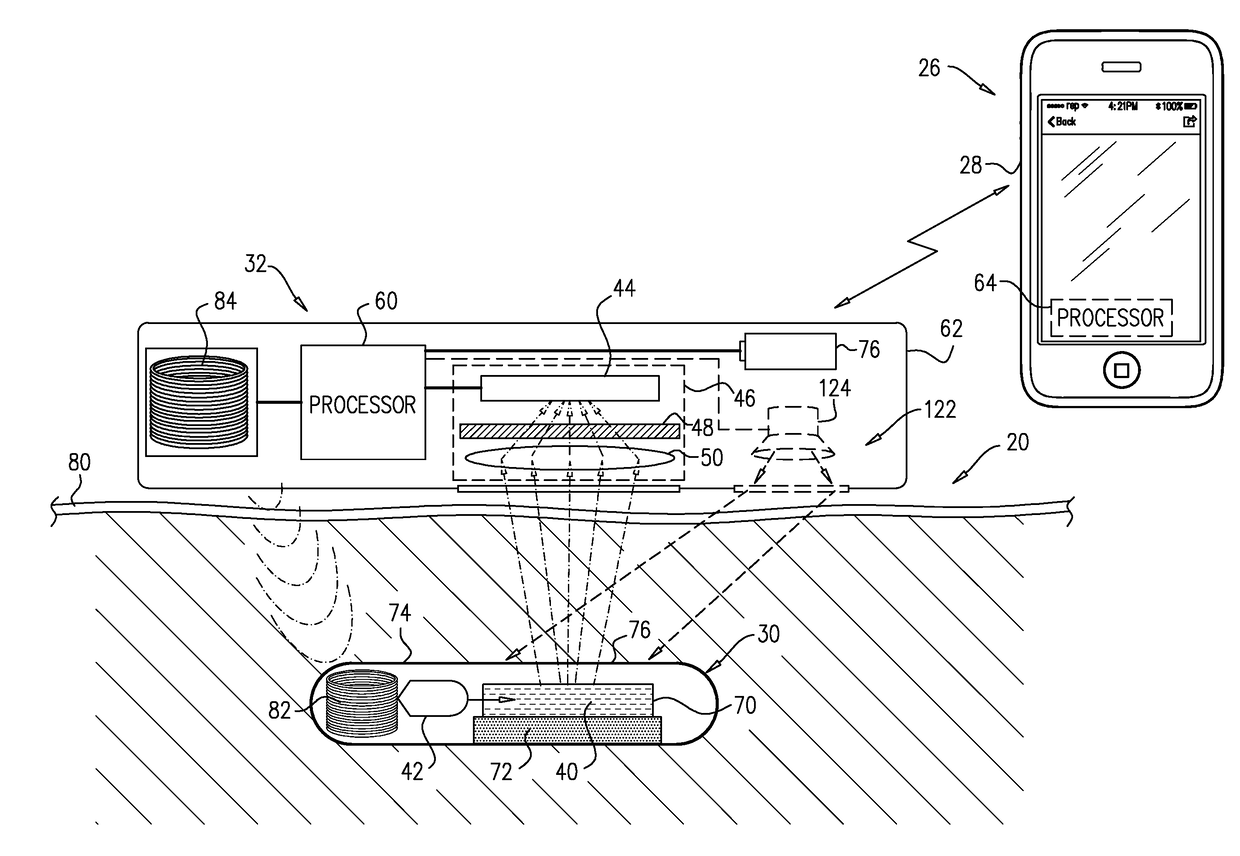
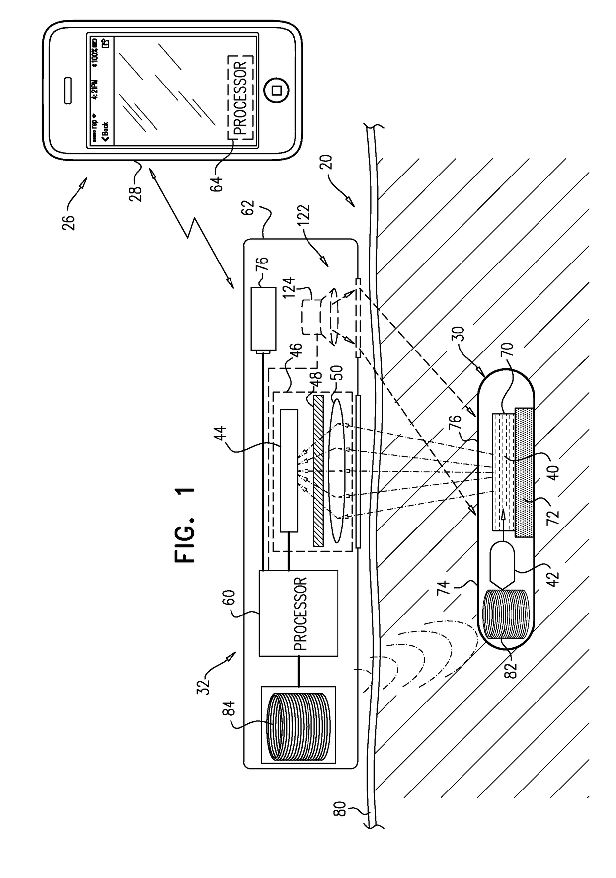
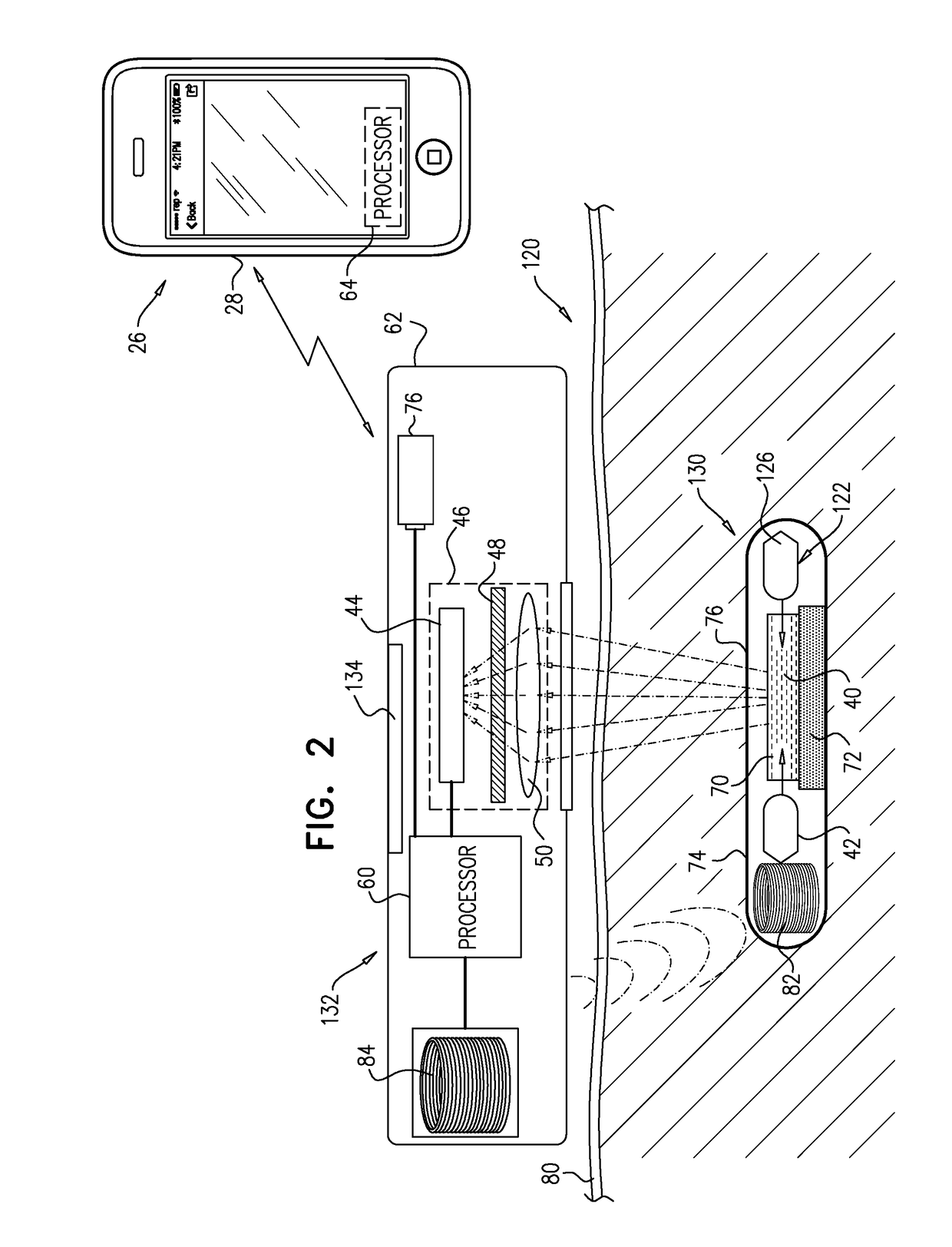
[0304]FIG. 1 is a schematic illustration of a system 20 for transdermal detection of a concentration of an analyte in a subject, in accordance with an application of the present invention. System 20 comprises an implantable unit 30, which is configured to be implanted in a body of the subject, and an external system 26, which is physically separate and distinct from implantable unit 30. External system 26 comprises an external reading unit 32 and, optionally, an external monitor unit 28.

[0305]Implantable unit 30 comprises fluorescent sensor molecules 40, each of which comprises a binding site for the analyte, and at least one fluorescent moiety. A number of fluorescent compounds have been described in the literature for the purpose of analyte sensing, including different fluorescent reporters, e.g., Concanavalin-A, fluorescein, and fluorophores derived from various marine fauna, such as GFP and its derivatives. The analyte sensing is based on different mechanisms, including, e.g., s...


PUM


Abstract

An implantable unit includes fluorescent sensor molecules, each of which includes a binding site for an analyte, a donor fluorophore, and an acceptor fluorophore; and a first light source. An external system includes an external reading unit, which includes a light sensor; and a processor, which is configured to (i) during a first time period: (a) drive the first light source to generate light having a first illumination peak wavelength appropriate for excitation of the donor fluorophore, and (b) receive, from the light sensor, a first measurement of the fluorescent light emitted from the acceptor fluorophore, (ii) during a second time period: (a) drive a second light source to generate light having a second illumination peak wavelength appropriate for direct excitation of the acceptor fluorophore, and (b) receive, from the light sensor, a second measurement of the fluorescent light emitted from the acceptor fluorophore, and (iii) calculate the concentration of the analyte based on the measurements.

Description

CROSS-REFERENCE TO RELATED APPLICATIONS[0001]The present application claims priority from U.S. Provisional Application 62 / 063,211, filed Oct. 13, 2014, which is assigned to the assignee of the present application and is incorporated herein by reference.FIELD OF THE APPLICATION[0002]Some applications of the present invention relate generally to implantable sensors for detecting an analyte in a body and specifically to methods and apparatus for reading the optical signal from an implantable medical device.BACKGROUND OF THE APPLICATION[0003]The monitoring of various medical conditions often requires measuring the levels of various components within the blood. In order to avoid invasive repeated blood drawing, implantable sensors aimed at detecting various components of blood in the body have been developed. More specifically, in the field of endocrinology, in order to avoid repeated “finger-sticks” for drawing blood to assess the levels of glucose in the blood in patients with diabetes...

Claims


Application Information

Patent Timeline
IPC IPC(8): A61B5/1455A61B5/145A61B5/00A61B5/1459G01N21/64
CPCA61B5/14556A61B5/0071A61B5/14532G01N2201/021G01N21/6428G01N21/6456A61B5/1459
Inventor BRILL, BOAZ
Owner GLUSENSE LTD
Why Eureka
Try Eureka