

Magnetic field generator
A magnetic field generator and magnetic field technology, applied in the direction of permanent magnets, etc., can solve the problems of small magnetic field adjustable range, large magnetic flux leakage, etc., and achieve the effect of large magnetic field adjustment range, small volume, and less magnetic source consumption
- Summary
- Abstract
- Description
- Claims
- Application Information
AI Technical Summary
Problems solved by technology
Method used
Image

Examples
Embodiment 1
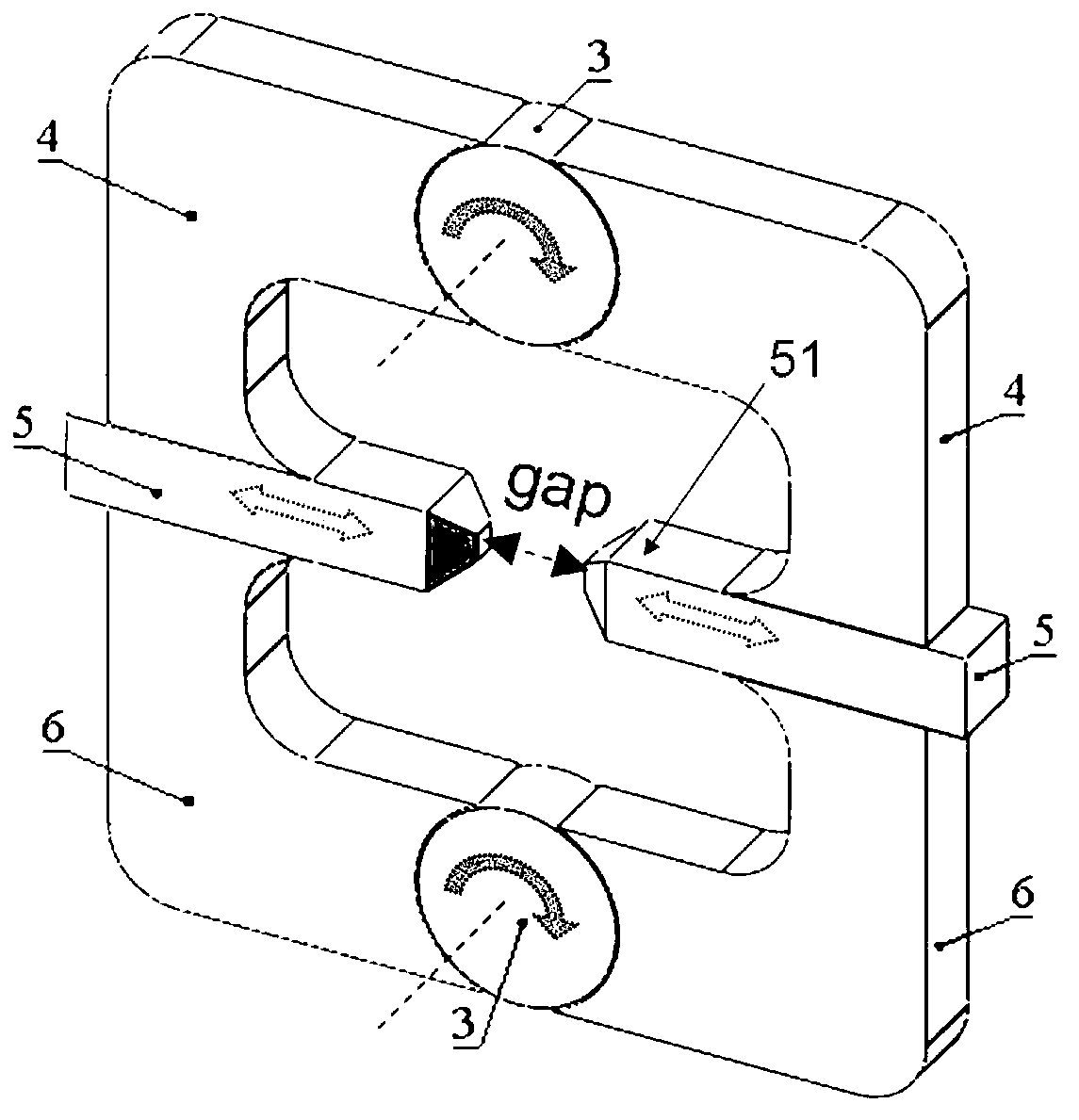
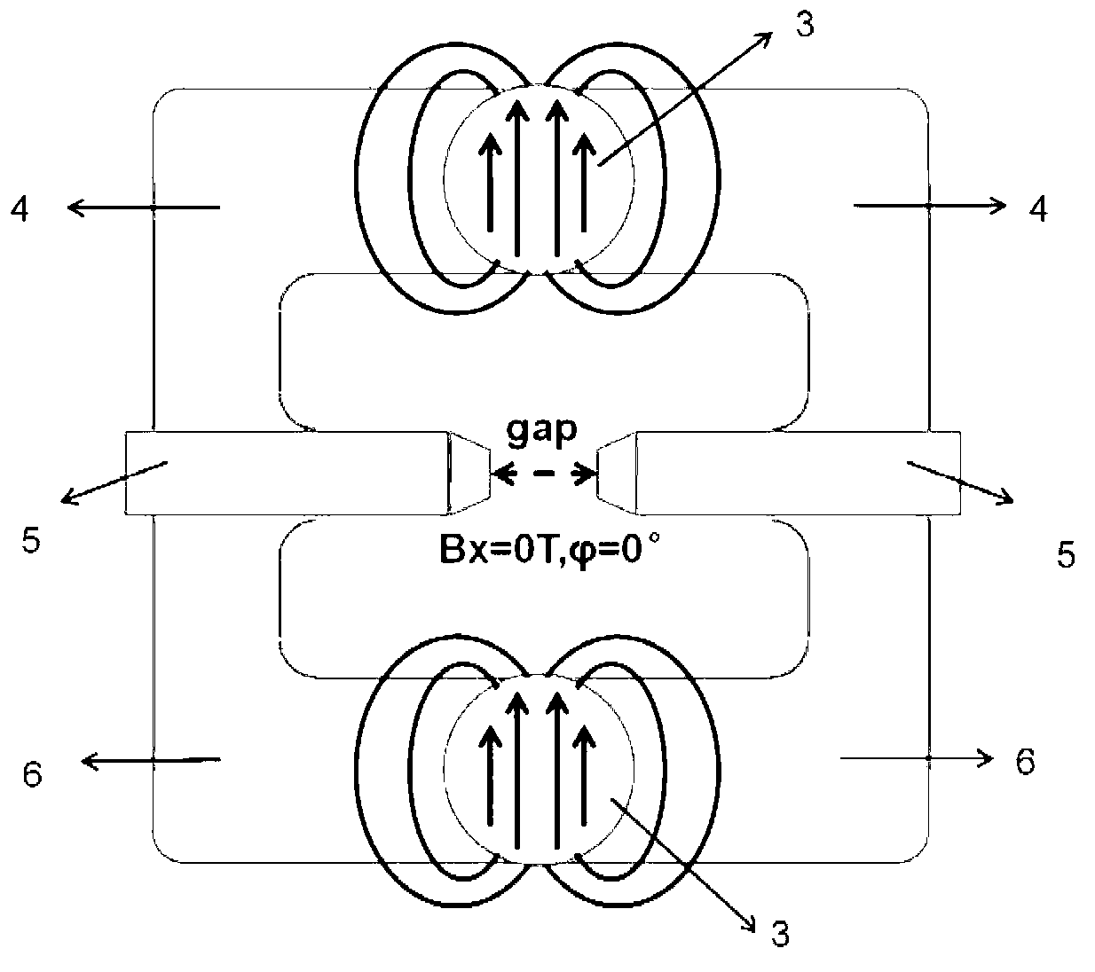
[0036] This embodiment provides a linear adjustable magnetic field generator, its structure is as follows figure 2 shown, including:
[0037] Two cylindrical permanent magnets 3, made of N48H high-performance NdFeB permanent magnet material, with a diameter of 14mm and a height of 6mm, are radially magnetized, and the radial magnetic field strength is about 0.58T;
[0038] Two strip-shaped magnetically conductive pole heads 5 each have a terraced pole head end 51, and the two pole head ends 51 are placed oppositely to generate a magnetic field in the air gap gap between the two pole head ends 51;
[0039] The first and second magnetically conductive yokes 4 and 6 are U-shaped, and the U-shaped bottom edge has a circular opening, and the above-mentioned two cylindrical permanent magnets 3 are respectively fixed in the two circular openings, and can Radial rotation, the two ends of the first and second magnetically permeable yokes 4 and 6 are respectively connected to two bar-...
Embodiment 2
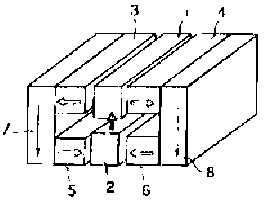
[0045] This embodiment provides a linearly adjustable magnetic field generator, which includes the structure of the linearly adjustable magnetic field generator in Embodiment 1. The structure of the magnetic field generator provided by this embodiment is as follows Figures 7a-7c shown (with figure 2 In the same parts with the same reference numerals), as in figure 2 The outside of the structure of the magnetic field generator shown also includes:
[0046] Aluminum housing for housing such as figure 2 The magnetic field generator shown, the aluminum housing includes a frame part 2 and two side plate parts 1 (where Figure 7a and 7b Only one side plate 1 on the front side is shown in the figure), and the inner space of the aluminum housing is defined by the frame part 2 and the two side plate parts 1 to accommodate the magnetically permeable yoke 4, the permanent magnet 3 and the magnetically permeable poles The head 5, wherein the magnetically conductive yoke 4 is fixed...
Embodiment 3
[0050] This embodiment provides a linear adjustable magnetic field generator, its structure is as follows Figure 8 shown, including:
[0051] Cylindrical permanent magnet 33, radially magnetized;
[0052] Two strip-shaped magnetically conductive pole heads 35 have pole ends 351 respectively. The cross-section of the pole ends 351 is elliptical, and the two pole ends 351 are placed oppositely to generate a magnetic field in the air gap gap between the two pole ends 351;
[0053] U-shaped magnetic yoke 36, the U-shaped base has a circular opening, the above-mentioned cylindrical permanent magnet 33 is fixed in the circular opening, and can rotate radially, and the two ends of the magnetic yoke 36 are respectively Connected to two bar-shaped magnetically conductive pole heads 35, forming a closed magnetic flux loop with the two bar-shaped magnetically conductive pole heads 35, for conducting the magnetic field of the cylindrical permanent magnet 33 to the air gap gap between th...
PUM
| Property | Measurement | Unit |
|---|---|---|
| Diameter | aaaaa | aaaaa |
Abstract
Description
Claims
Application Information