Axle lifting device for a vehicle

a technology for lifting devices and axles, applied in the direction of loading/unloading vehicle arrangments, transportation items, cycles, etc., can solve the problems of more space for components installed in the vicinity of the wheel shaft, the location of the air bellows preventing the installation of components,

Inactive Publication Date: 2002-08-20
SCANIA CV AB
View PDF16 Cites 7 Cited by
  • Summary
  • Abstract
  • Description
  • Claims
  • Application Information

AI Technical Summary

Problems solved by technology

As such a vehicle incorporates a multiplicity of components which have to be accommodated or which it is appropriate to install in the vicinity of such a wheel shaft, this location of the air bellows constitutes an obsta...

Method used


Image

  • Axle lifting device for a vehicle
  • Axle lifting device for a vehicle
  • Axle lifting device for a vehicle

Examples


Embodiment Construction

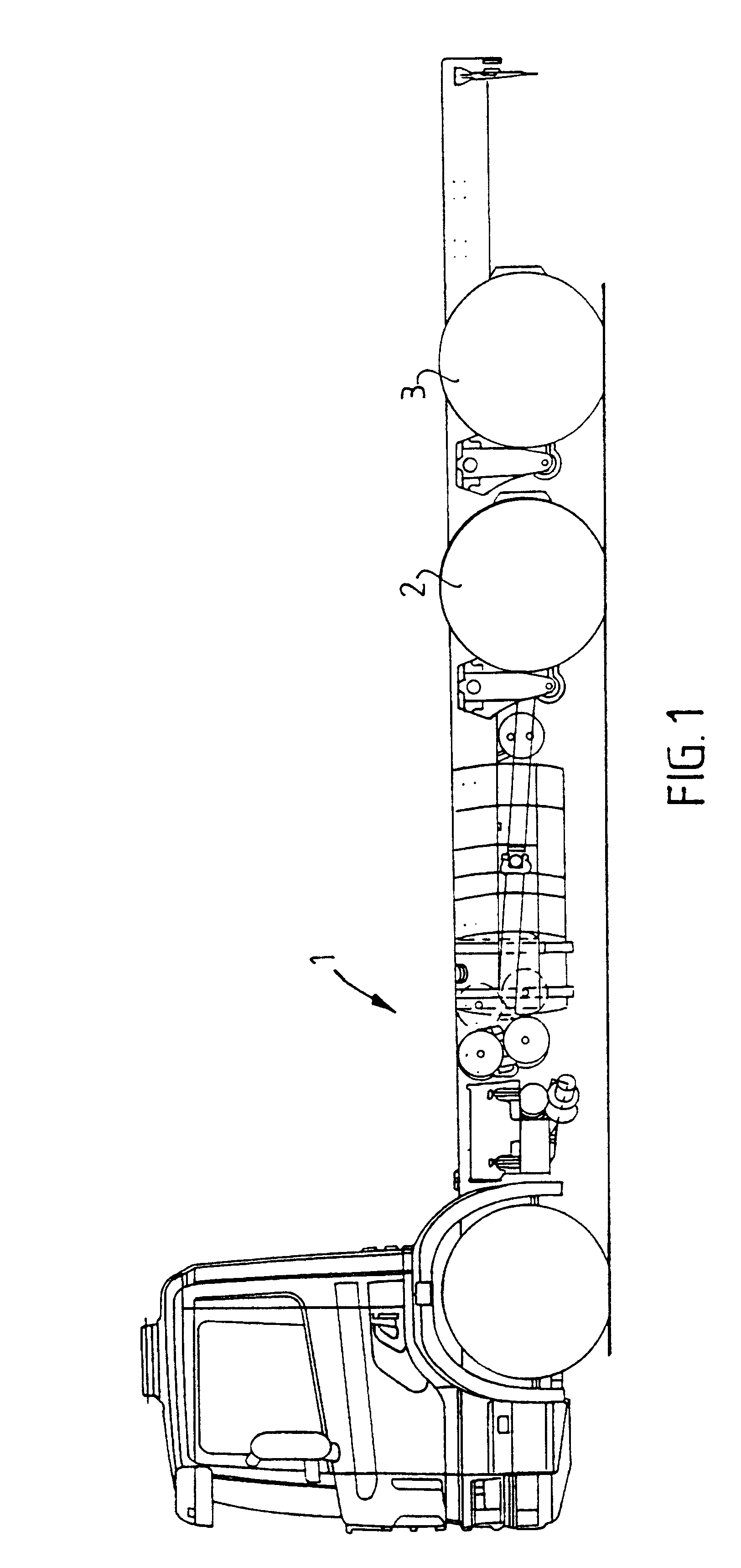
FIG. 1 shows a load-carrying vehicle 1 on which a lifting arrangement according to the invention is applicable. The vehicle 1 incorporates under its load-carrying surface a first wheel shaft with driven wheels 2 and a second wheel shaft with undriven wheels 3. When the vehicle 1 travels unladen, the wheels 3 of the rear wheel shaft may be raised from the ground. The driving wheels 2 are thereby provided with a better driving grip on the roadway. When the vehicle 1 is heavily laden, the wheels 3 are lowered to the ground so that the heavy load is distributed between the driven wheels 2 of the first shaft and the wheels 3 of the second shaft.

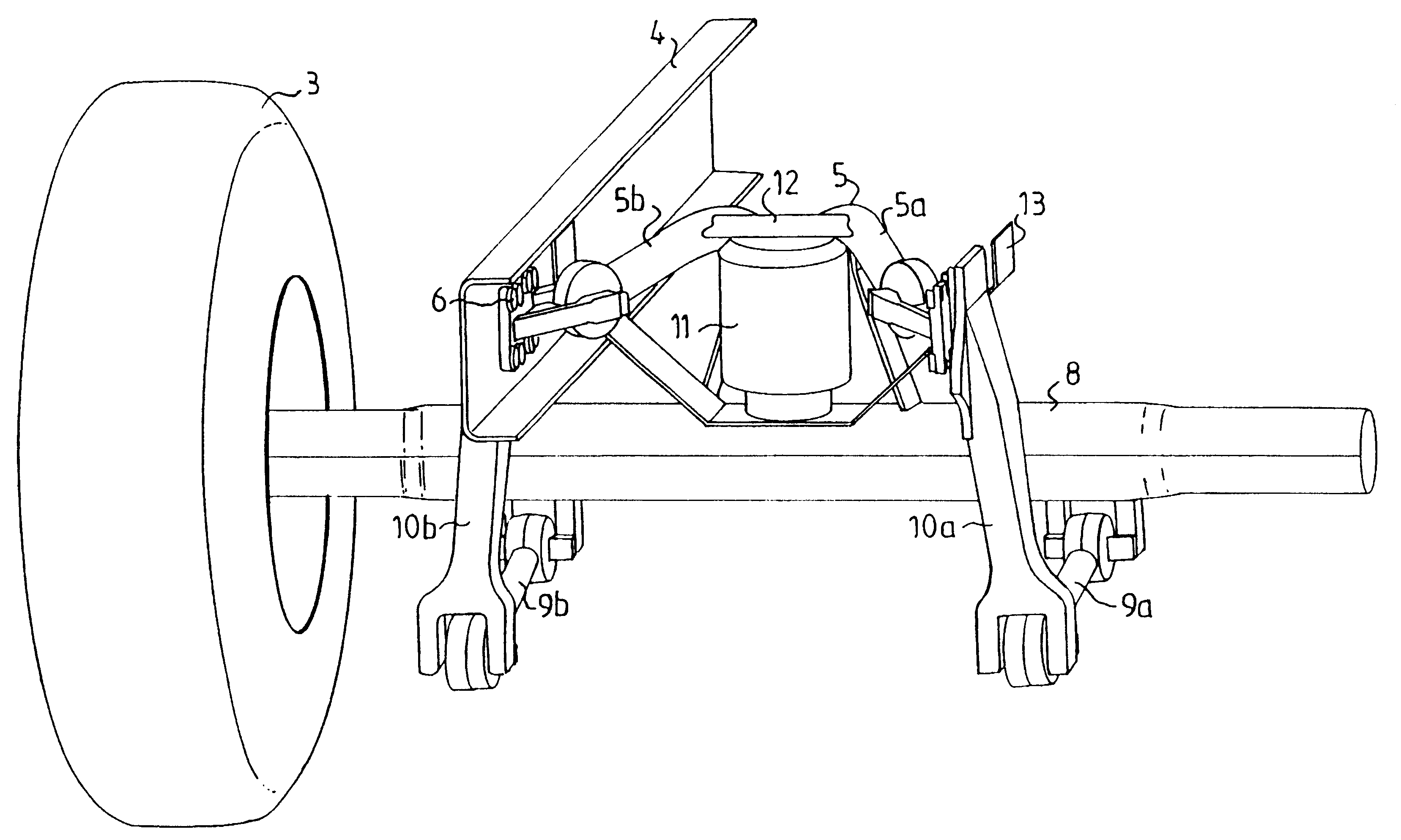
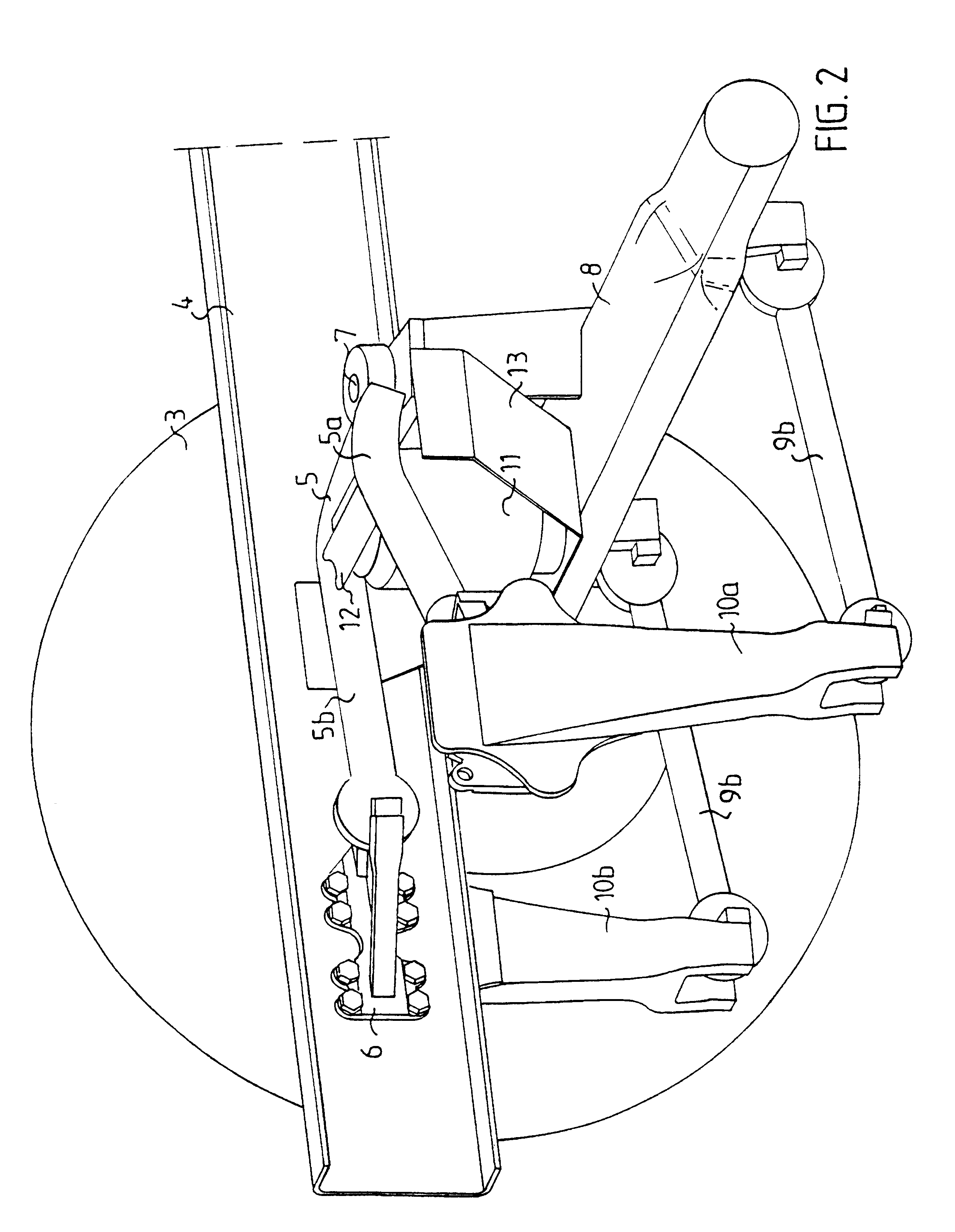
FIGS. 2 and 3 show an embodiment of the lifting arrangement according to the invention. The vehicle 1 incorporates two frame side-members 4 extending in its longitudinal direction, only one of which is depicted in the drawings. A substantially V-shaped upper stay device 5 which incorporates two stay elements 5a, 5b is fastened in the frame side-me...


PUM


Abstract

A lifting arrangement for a wheel shaft of a vehicle operates on a wheel shaft that is movably suspended in a vehicle frame structure through one or more stay devices. The stay devices are articulatedly connected to the frame structure through at least one frame connection, and to the wheel shaft by at least one shaft connection. A lifting device is arranged in connection with the frame structure and the stay device to raise the wheel shaft in a vertical direction relative to the frame structure when actuated. The stay device provides a compact mechanism to permit the vehicle axle to be lifted, while preserving room for other vehicle components.

Description

BACKGROUND TO THE INVENTION, AND STATE OF THE ARTThe invention relates to a lifting arrangement for a wheel shaft of a vehicle articulated stays for raising the wheel vertically.Such lifting arrangements of wheel shafts of vehicles are previously known, inter alia, on load-carrying vehicles which incorporate under their load surface two wheel shafts, viz. one driving shaft and one supporting shaft. In an unloaded state the load-carrying vehicle travels mostly with the supporting shaft raised so that the wheels of the driving shaft obtain a good driving grip on the roadway. In a loaded state the supporting shaft is lowered so that the load carried can be distributed over the wheels of both shafts.Such lifting arrangements incorporate a lifting device, usually in the form of an air bellows arranged between the vehicle's frame structure and the supporting shaft. The wheel suspension of such a supporting shaft usually incorporates an upper V-shaped reaction stay which extends between th...

Claims


Application Information

Patent Timeline
IPC IPC(8): B62D61/12B62D61/00
CPCB62D61/12B60G2204/4702
Inventor KARLSSON, PETER
Owner SCANIA CV AB
Why Eureka
Try Eureka