Jet-weaving machine, particularly an air jet-weaving machine, with a clamping device in the mixing tube

a jet-weaving machine and mixing tube technology, which is applied in the field of jet-weaving machines, can solve the problems of inability to individually control the clamping or holding device, the weft thread is imparted a pinch which no longer readily comes loose, and the weft thread is relatively easy to loosen. , to achieve the effect of easy insertion into the shed

Inactive Publication Date: 2009-05-26
LINDAUER DORNIER GMBH
View PDF24 Cites 4 Cited by
  • Summary
  • Abstract
  • Description
  • Claims
  • Application Information

AI Technical Summary

Benefits of technology

[0027]According to a development of the invention, in a jet-weaving machine which is provided for a multicolor fabric, the main blow nozzles together with their mixing tubes are combined into a block having up to eight main blow nozzles and respective mixing tubes. In this block, preferably, in each case two mixing tubes lying directly next to one another are provided on each of their sides facing away from one another with an actuator having a lever, that is to say the mixing tubes carry an actuator having a lever on each of their sides facing away from one another, that is to say in a 180° arrangement. Preferably, these two actuators are combined into a modular unit, that is to say in pairs. Preferably, the modular unit is a frame-shaped design and consequently surrounds the two actuators with their corresponding levers. It is consequently possible to provide four such modular units, each with a pair of actuators and associated levers, in the direct outlet orifice region of the mixing tubes, without the individual mixing tubes having to be arranged far apart from one another due to the arrangement of the actuator and lever. The compact arrangement of the number of mixing tubes has the advantage that the respective colors or various materials of weft threads can easily be inserted into the shed in spite of the multiple arrangement.

Problems solved by technology

On the other hand, the disadvantage of clamping the weft thread even upstream of the main nozzle is that clamping imparts to the weft thread a pinch which no longer readily comes loose in the case of specific materials after the insertion of the weft thread, so that this clamping can be detected at least visually in the finished fabric.
This, however, would result in a relatively high loss of material.
An individual control of the clamping or holding device is not possible.

Method used


Image

  • Jet-weaving machine, particularly an air jet-weaving machine, with a clamping device in the mixing tube
  • Jet-weaving machine, particularly an air jet-weaving machine, with a clamping device in the mixing tube
  • Jet-weaving machine, particularly an air jet-weaving machine, with a clamping device in the mixing tube

Examples


Embodiment Construction

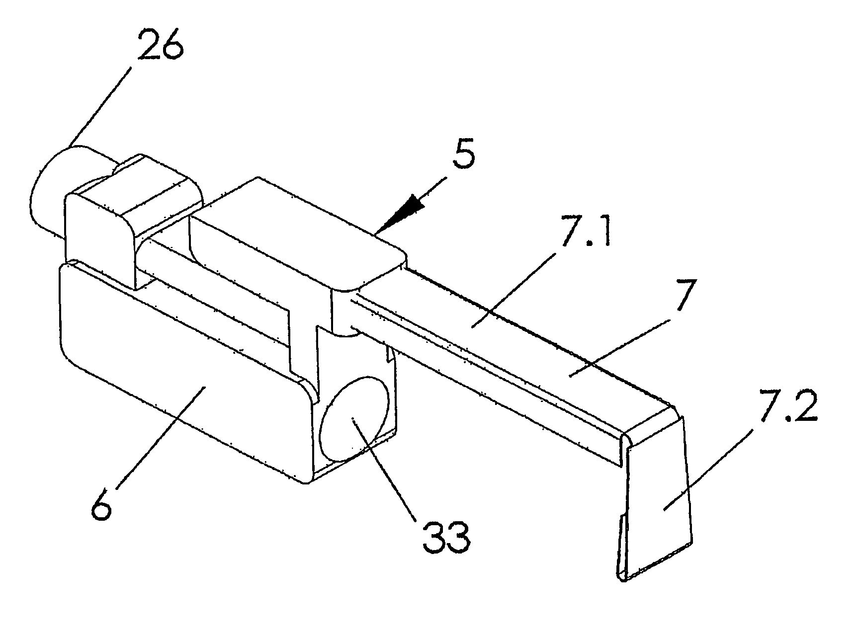
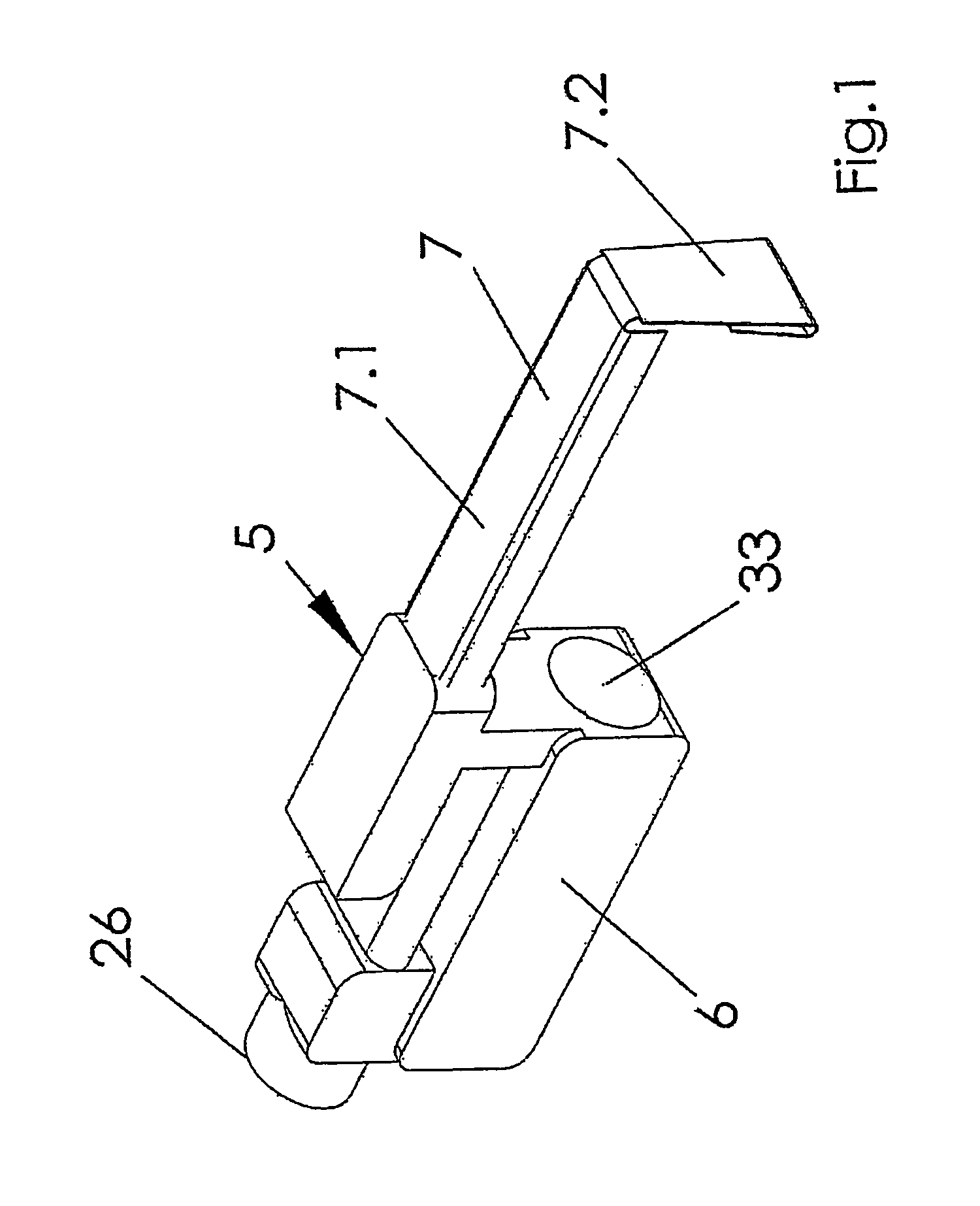
[0064]FIG. 1 illustrates an essential part of the clamping device 5 in the preassembled state. An elastomeric bellows or concertina designed as a hollow profile forms the actuator 6 which can be supplied with actuation means or actuation medium such as compressed air via a connection or port 26. A lever 7 with a long leg 7.1 and with a short leg 7.2 is plugged at its end with the long leg 7.1 onto the actuator 6 by means of a profiling, not designated. The actuator 6 itself has a passage duct 33 of circular cross section, which serves for plugging the actuator firmly onto a mixing tube (not shown). The diameter of this passage duct 33 is in this case dimensioned such that the actuator 6, after being mounted, sits firmly on the mixing tube. The angled short leg 7.2 of the lever 7 is folded at its lower end onto itself over part of its length, so that at its lower end there is a radius at which the actual clamping of the weft thread (not shown) takes place. The weft thread is clamped ...


PUM


Abstract

A thread clamping device is provided for a jet weaving machine that has a main discharge nozzle (1) with a mixing tube (2) for inserting a weft thread (3) into a shed with a conveying fluid discharged from the main discharge nozzle. This clamping device is placed inside the mixing tube (2) in the area from which the weft thread exits, and has an actuator, which is situated outside of the mixing tube (2), and a lever connected to the actuator so that this lever is actuated by the actuator (6) to execute a tilting or pivoting motion whereby the weft thread is clamped between the lever and an abutment (9) in an opening of the mixing tube.

Description

TITLE OF THE INVENTION[0001]Jet-weaving machine, particularly an air jet-weaving machine, with a clamping device in the mixing tubeFIELD OF THE INVENTION[0002]The invention relates to a jet-weaving machine, particularly an air jet-weaving machine, with a clamping device in the mixing tube for clamping a cut-off weft thread in such a way that the latter is prevented from jumping back into the mixing tube.BACKGROUND INFORMATION[0003]Jet-weaving machines, particularly air jet-weaving machines, belong to shuttleless weaving machines. A shuttleless weaving machine of this type is known from DE 32 00 638 A1. In this known shuttleless weaving machine, either a thread clamp is arranged in the end region of the mixing tube of a main blow nozzle mounted on the batten or, in addition to this, a further thread clamp is arranged upstream of the entry of the weft thread into the main blow nozzle. The known thread clamps are designed as an elastic intermediate piece which is inserted firmly into t...

Claims


Application Information

Patent Timeline
Patent Type & Authority Patents(United States)
IPC IPC(8): D03D47/28D03D47/30D03D47/32D03D41/00D03D47/34
CPCD03D47/3013D03D47/3053
Inventor GIELEN, MARKUSLAUKAMP, THOMAS
Owner LINDAUER DORNIER GMBH
Why Eureka
Try Eureka