Privacy latch

a technology of latches and privacy, applied in the field of door fittings, can solve the problems that the latches cannot be used with the cavity sliding door, and the handles are not suitable for the use of the cavity sliding door, and achieve the effect of reducing parts and smooth operation of the lock

Inactive Publication Date: 2012-11-22
JACOU IND ZHONGSHAN
View PDF36 Cites 3 Cited by
  • Summary
  • Abstract
  • Description
  • Claims
  • Application Information

AI Technical Summary

Benefits of technology

[0010]An object of the present disclosure is to provide a smooth operating lock having reduced parts.

Problems solved by technology

In particular, protruding handles are not suitable for use with cavity sliding doors, that is, door panels which are typically hidden from view by sliding them into a wall cavity.

Method used


Image

  • Privacy latch
  • Privacy latch
  • Privacy latch

Examples


Embodiment Construction

[0047]List of parts:

[0048]1 latch mechanism

[0049]5 latch body

[0050]7 drive member

[0051]8 cam

[0052]10 spindle

[0053]12 link

[0054]15 hook

[0055]17 guide

[0056]19 face plate

[0057]21 over center spring

[0058]23 recessed cups

[0059]25 lever

[0060]26 strike plate

[0061]27 bolt head

[0062]28 strike plate assembly

[0063]29 spring (for spring loaded tongue 31)

[0064]31 tongue

[0065]33 recessed plate

[0066]35 latch casing

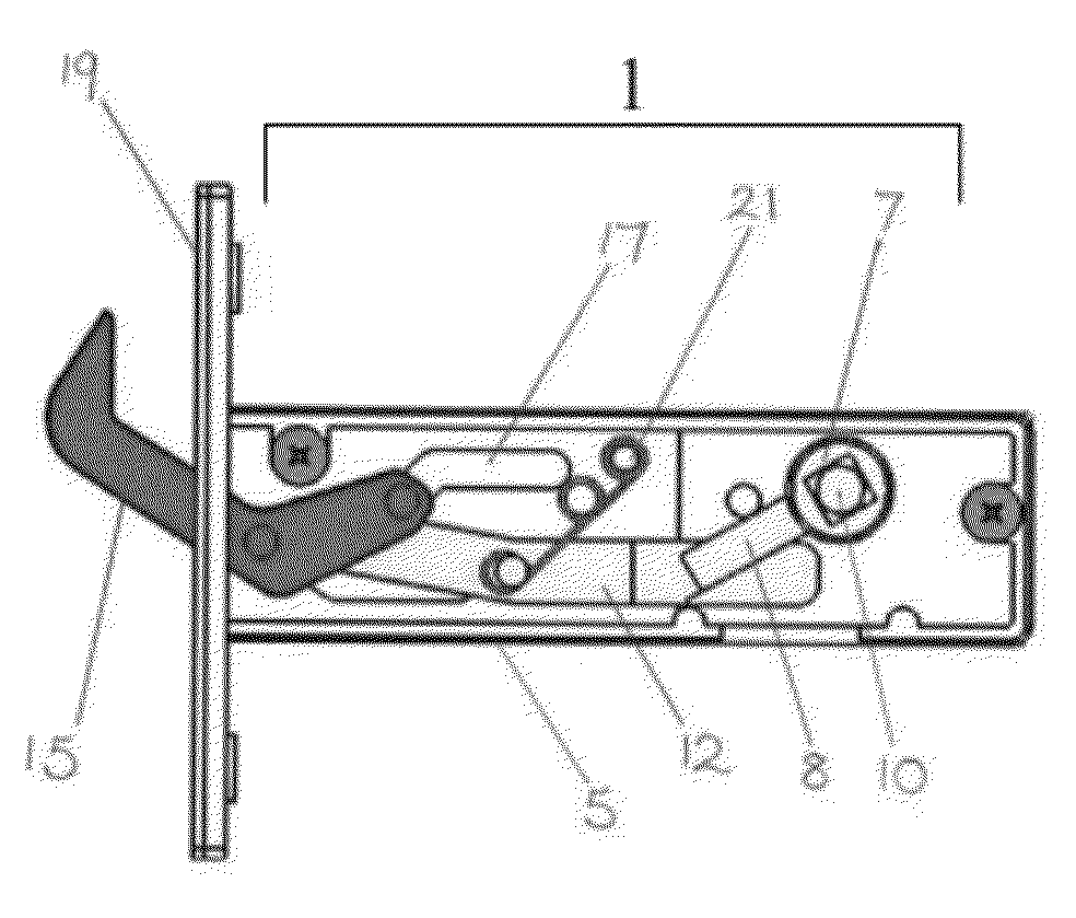
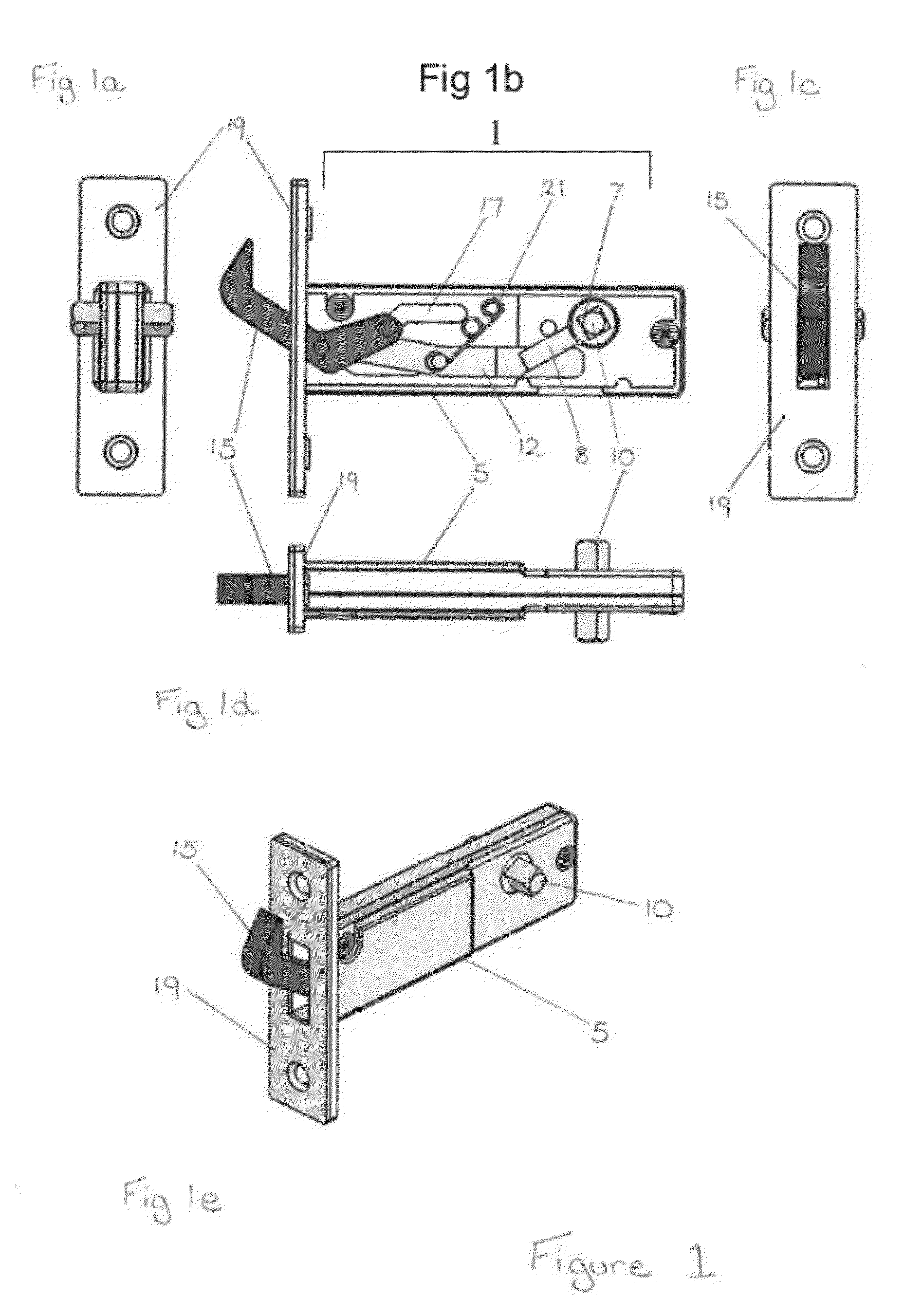
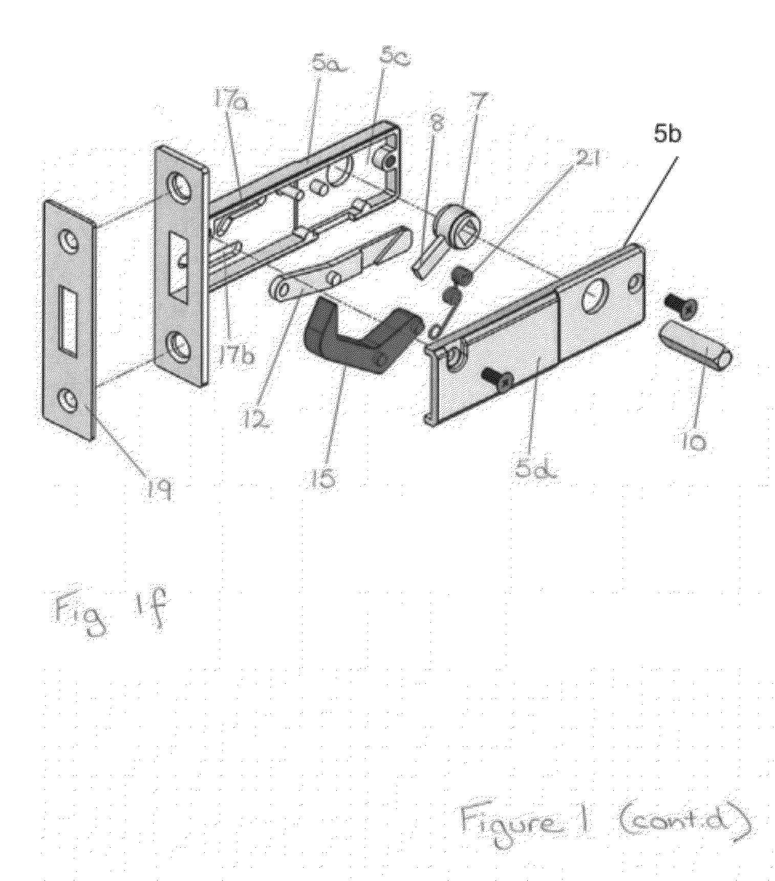
[0067]FIG. 1 depicts a latch mechanism (1) latch body (5) supporting a drive member (7) having a cam (8) adapted for movement in response to rotation of a spindle (10).

[0068]The latch body (5) is generally of rectangular cross section, having a parallel top and bottom surface (5a, 5b) and parallel side surfaces (5c,5d). A link (12) imparts movement between the drive member (7) and a hook (15). In this embodiment the link (12) has a first end cooperating with a cam (8) integral with the drive member (7) and a second end cooperating with the hook (15).

[0069]The hook movement follows the gu...


PUM


Abstract

The present disclosure relates to the field of door fittings, particularly door fittings comprising a privacy latch for a sliding door. In one particular aspect the present disclosure is suitable for use for securing interior or exterior doors, including doors for bathrooms, changing rooms, shower or toilet cubicles to give users the option of privacy. The present disclosure stems from the realization that smooth movement of a latch hook between a locked and unlocked condition can be obtained by use of a guide.

Description

RELATED APPLICATIONS[0001]The present application claims priority to Australian Provisional Patent Application Number 2011901916, filed on May 18, 2011, the entire contents of which are hereby incorporated by reference for all purposes.FIELD[0002]The present disclosure relates to the field of door fittings, particularly door fittings comprising a privacy latch for a sliding door. In one particular aspect the present disclosure is suitable for use for securing interior or exterior doors, including doors for bathrooms, changing rooms, shower or toilet cubicles to give users the option of privacy.[0003]It will be convenient to hereinafter describe example embodiments in relation to specific types of doors, however it should be appreciated that the present disclosure is not limited to that use only and can be used in a wide range of applications.BACKGROUND ART[0004]It is to be appreciated that any discussion of documents, devices, acts or knowledge in this specification is included to e...

Claims


Application Information

Patent Timeline
Patent Type & Authority Applications(United States)
IPC IPC(8): E05C19/12E05C5/00
CPCE05B65/0035E05B15/022E05C5/00E05B65/0817Y10T292/0914Y10T292/0915
Inventor SAUNDERS, JOHN DAVIDWU, YAN GAO
Owner JACOU IND ZHONGSHAN
Why Eureka
Try Eureka