Display panel

a technology for display panels and substrates, applied in the field of display panels, can solve the problems of peeling off sealing materials, reducing the adhesion between sealing materials and substrates, etc., and achieves the effects of reducing the increase in cost, uniform thickness of display medium layers, and excellent properties

Inactive Publication Date: 2012-04-05
SHARP KK
View PDF6 Cites 14 Cited by
  • Summary
  • Abstract
  • Description
  • Claims
  • Application Information

AI Technical Summary

Benefits of technology

[0012]The present invention has been made in view of the foregoing, and it is an objective of the present invention to provide a display panel in which reduction in adhesion between a sealing material and a substrate is prevented and narrowing of a picture-frame region can be realized by a suitable amount of the sealing material.
[0029]According to the present invention, the disadvantage that the sealing material is peeled off can be prevented, and t he increase in cost can be reduced to realize the narrowing of the picture-frame region by the suitable amount of the sealing material.

Problems solved by technology

As a result, a problem is caused, in which adhesion between the sealing material and the substrate is reduced, thereby peeling off the sealing material.

Method used


Image

  • Display panel
  • Display panel
  • Display panel

Examples


Embodiment Construction

[0055]Embodiments of the present invention will be described below in detail with reference to the drawings. Note that the present invention is not limited to the embodiments below.

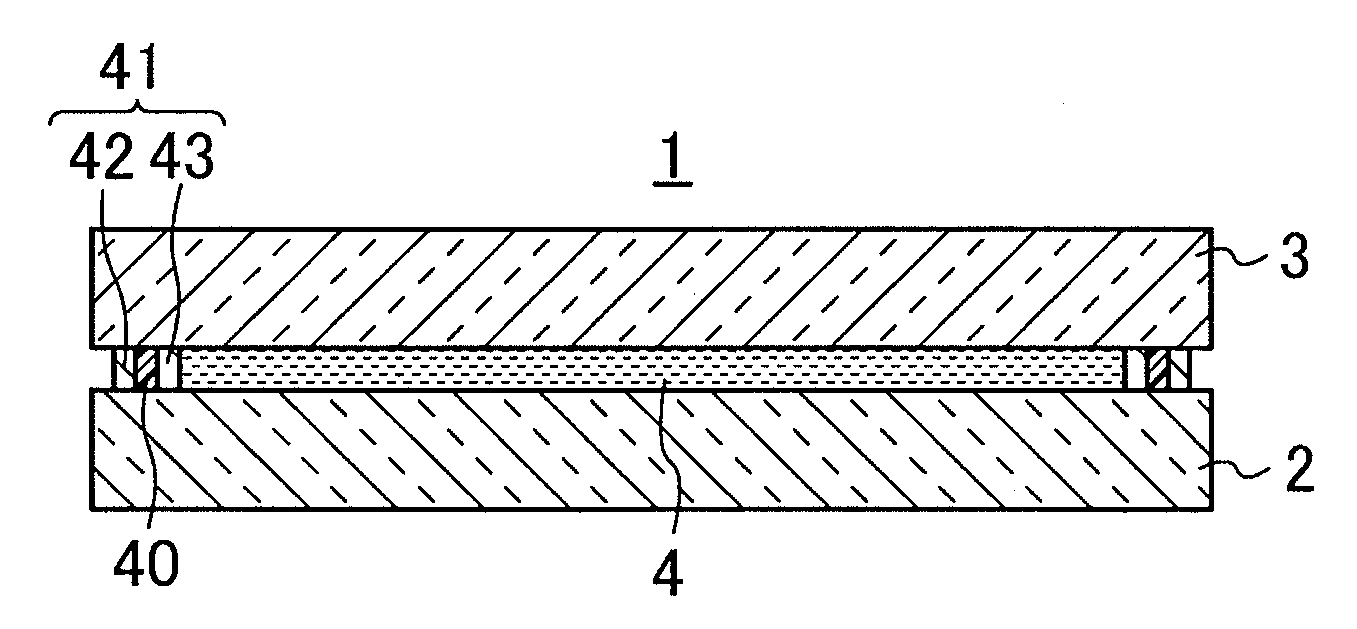
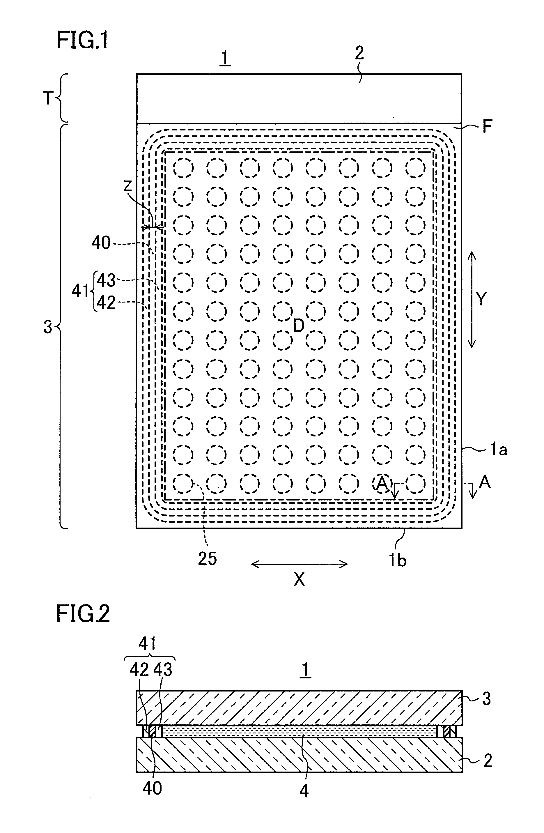
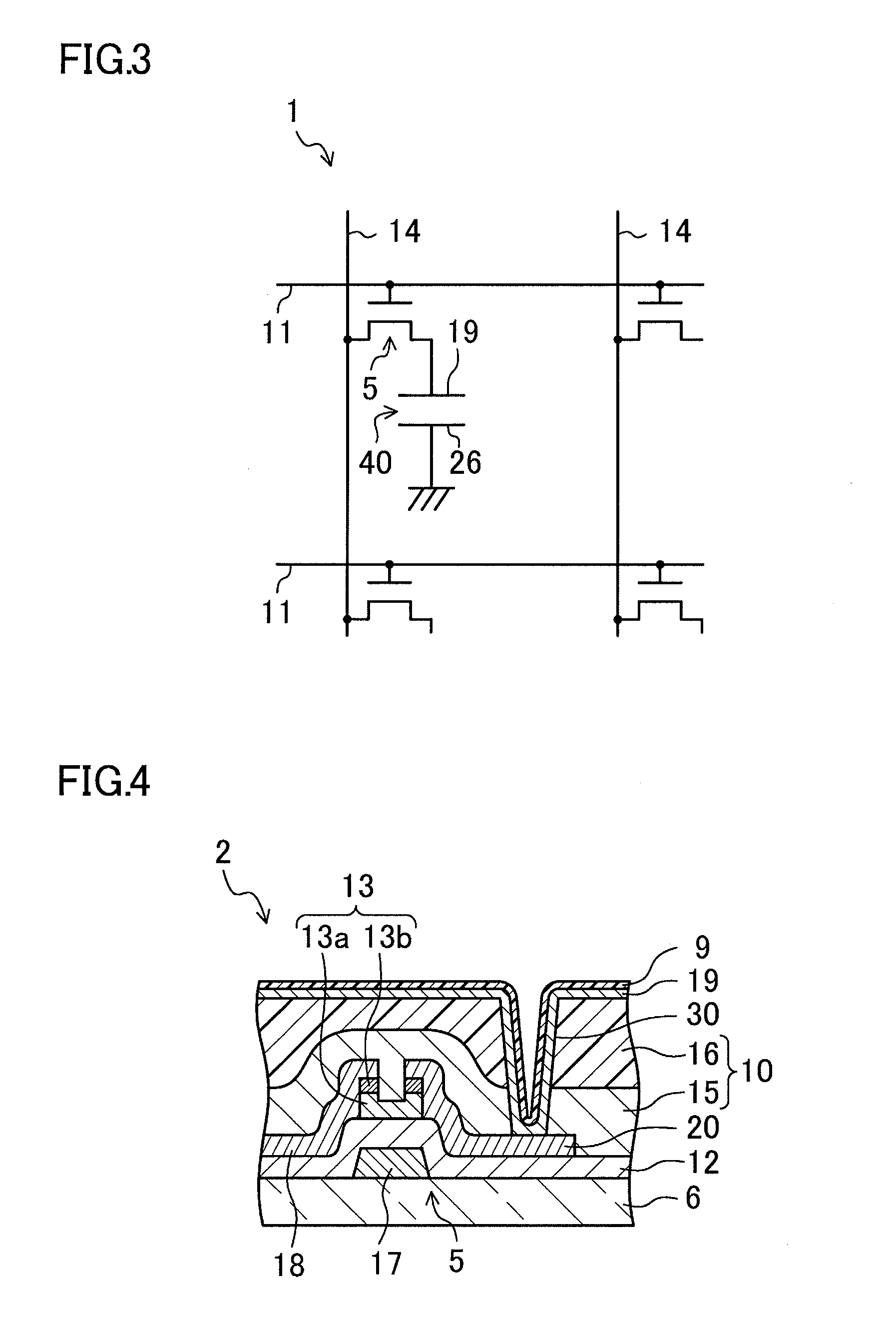
[0056]FIG. 1 is a plan view illustrating an entire configuration of a liquid crystal display panel of a first embodiment of the present invention, and FIG. 2 is a cross-sectional view of the liquid crystal display panel of the first embodiment of the present invention. In addition, FIG. 3 is an equivalent circuit diagram of the liquid crystal display panel of the first embodiment of the present invention, and FIG. 4 is a cross-sectional view illustrating an entire configuration of a TFT substrate forming the liquid crystal display panel of the first embodiment of the present invention. Further, FIG. 5 is a cross-sectional view illustrating an entire configuration of a display section of the liquid crystal display panel of the first embodiment of the present invention, and FIG. 6 is a cross-sectional view ...


PUM

PropertyMeasurementUnit
widthaaaaaaaaaa
widthaaaaaaaaaa
thicknessaaaaaaaaaa

Abstract

In a picture-frame region (F) of a liquid crystal display panel (1), a wall member (41) is provided, which is formed adjacent to a sealing material (40) and sandwiches the sealing material (40). Steps (42a), (43a) are formed in the wall member (41) so that a width (W1) of a portion (40a) of the sealing material (40), which contacts a TFT substrate (2) is larger on a side on which the sealing material (40) contacts the TFT substrate (2).

Description

REFERENCE TO RELATED APPLICATIONS[0001]This application is a national stage application under 35 USC 371 of international Application No. PCT / JP2010 / 002380, filed Mar. 31, 2010, which claims the priority of Japanese Application No. JP2009-162397, filed Jul. 9, 2009, the contents of which prior applications are incorporated here by reference.FIELD OF THE INVENTION[0002]The present invention relates to a display panel such as a liquid crystal display panel in which a pair of substrates are stacked with a predetermined clearance and liquid crystal is sealed in the clearance between the pair of substrates.BACKGROUND OF THE INVENTION[0003]Since a liquid crystal display panel which is one of display panels is thin and light-weight, the liquid crystal display panel has been broadly used for mobile devices such as laptop computers and mobile phones and audio-visual equipment such as liquid crystal televisions.[0004]Typically, a liquid crystal display panel includes a pair of substrates (i.e...

Claims


Application Information

Patent Timeline
Patent Type & Authority Applications(United States)
IPC IPC(8): G02F1/1339
CPCG02F1/1339G02F1/133512G02F1/13394G02F2001/133337G03F7/0007G02F2001/13398G02F2001/13415G02F2201/501G02F2202/025G02F2001/133388G02F1/133337G02F1/133388G02F1/13415G02F1/13398
Inventor MISAKI, KATSUNORI
Owner SHARP KK
Why Eureka
Try Eureka